


15
English
Basic Connections (continued)
L
R
DIGITAL ANTENNA
RS-232
AUDIO OUTPUTVIDEO OUTPUT
COMPONENT
S-VIDEO
CVBS
PCM / DOLBY DIGITAL
COAXIAL
Manufactured under license from
Dobly Laboratories. “Dolby” and
the double-D symbol are
trademarks of Dolby Laboratories.
OPTICAL
ANALOG
HDMI
Y
L
R
P
b
Pr
1 2
RF IN RF IN
RF OUTTO TV
LOOP THROUGH
L
R
DIGITAL ANTENNA
RS-232
AUDIO OUTPUTVIDEO OUTPUT
COMPONENT
S-VIDEO
CVBS
PCM / DOLBY DIGITAL
COAXIAL
Manufactured under license from
Dobly Laboratories. “Dolby” and
the double-D symbol are
trademarks of Dolby Laboratories.
OPTICAL
ANALOG
HDMI
Y
L
R
P
b
Pr
1 2
RF IN RF IN
RF OUTTO TV
LOOP
THROUGH
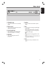
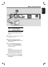
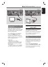
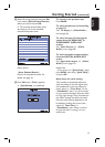
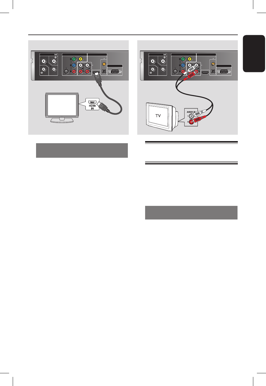
Step 3: Connecting the
audio cables
This connection enables you to listen to
the playback from this recorder.
However, this connection is not required
if this recorder is connected to the TV
using the HDMI connectors.
Option 1: Using the analogue audio
sockets
You can connect the recorder to a two
channel stereo system (mini system, TV)
or receiver in order to enjoy the stereo
sound system.
Use an audio cable (red/white) to
connect the AUDIO OUTPUT - L/R 1
or 2 sockets to the audio input sockets
of the connected device.
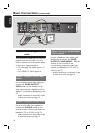
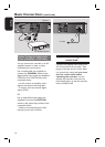
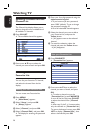
Option 4: Connecting to a HDMI
compatible TV
HDMI (High De nition Multimedia
Interface) is a digital interface that allows
pure digital video transmission without
the loss of image quality.
Use an HDMI cable (not supplied) to
connect the HDMI socket on this
recorder to the HDMI IN socket on a
HDMI compatible device (e.g. HDMI TV,
HDCP compliant DVI TV).
Helpful Hints:
– Digital devices from different
manufacturers may have different output
standards which may result in unreliable
signal transfers.
– The HDMI connector is only compatible
with HDMI compliant devices and DVI-TV.
Option 4 Option 1