


13
CONNECTING AN HD R
ECEIVER
T
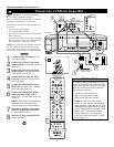
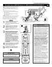
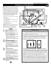
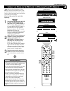
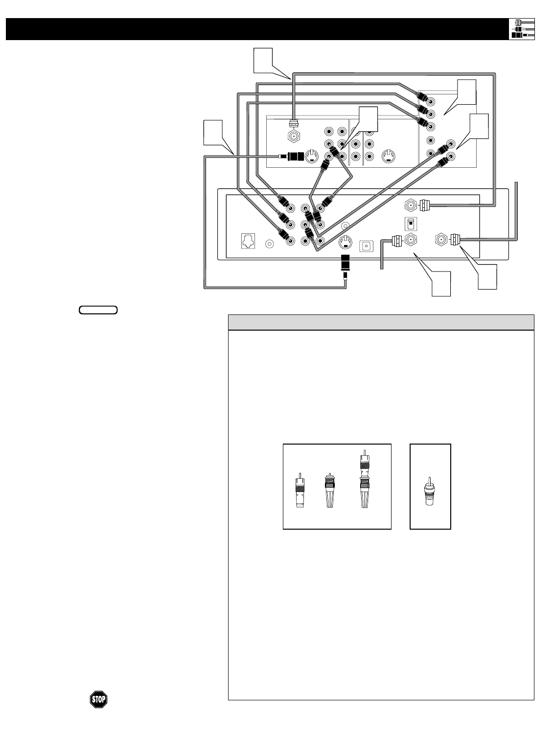
his example shows you how you may connect
an HD receiver to the TV. See the receiver’s
directions-for-use manual for more information.
NOTE: The HD INPUT-AV 4 jacks are designed
to accept high-definition signal standards 1080i
and 480p as specified by the Electronic Industries
Association standard EIA770.3. Because output
standards may vary by manufacturer, you may
encounter some digital equipment that will not
properly display pictures on the TV.
To make the connections shown in this example,
you will need:
• one S-VIDEO cable
• three cables for video connections (standard
RCA connectors)
• four cables for audio connections (standard
RCA connectors)
• one coaxial cable (75Ω).
NOTE: The cables are not supplied with your TV.
You should be able to buy them at most stores
that sell electronics. Or you can call our
Customer Care Center at 1-800-531-0039.
1
Connect S-VIDEO and audio cables.
NOTE: This example uses
INPUT-AV 1. You can use INPUT-AV 2 or
the side input jacks if you want.
• Connect an S-VIDEO cable from the HD
receiver’s S-VIDEO jack to the TV’s
INPUT-AV 1 S-VIDEO jack.
• Connect from the HD receiver’s AUDIO
L(eft) and R(ight) jacks to the TV’s
INPUT-AV 1 L(eft) and R(ight) AUDIO
jacks.
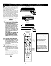
2
Connect component video and audio
cables to the TV’s HD inputs.
• Connect from the YPRPB jacks on the
HD receiver to the TV’s HD INPUT-AV
4 G/Y, R/Pr, B/Pb jacks.
• Connect from the HD receiver’s AUDIO
L(eft) and R(ight) jacks to the TV’s HD
INPUT-AV 4 L(eft) and R(ight) AUDIO
jacks.
3
Connect coaxial cables.
• Connect the coaxial cable lead-in from
your cable outlet, cable converter box, or
VHF/UHF antenna to the IN FROM
ANT jack on the HD receiver.
• Connect a coaxial cable from the OUT
TO TV jack to the ANTENNA IN 75Ω
jack on the TV.
• Connect the coaxial cable lead-in from a
satellite dish antenna to the SATELLITE
IN jack on the HD receiver.
4
Refer to the directions-for-use manual
that came with the HD receiver for setup
instructions.
VIDEO
S-VIDEO
L
Pb
Pr
VIDEO
S-VIDEO
L
AUDIO
L
R
AUDIO
L
R
G/Y
R/Pr
B/Pb
V
H
SYNC
L
R
AUDIO
HD INPUT-AV 4
INPUT-AV 2
OUTPUT
INPUT-AV 1
ANTENNA IN 75Ω
Y
Rear of TV
IN FROM ANT SATELLITE IN
OUT TO TV
CH 3
CH 4
DIGITAL
AUDIO OUT
VCR
CONTROL
S-VIDEO
VIDEOVIDEO
RR
PB
PR
Y
L
L
AUDIO
AUDIO
RF
REMOTEPHONE JACK
Coaxial Cable
Lead-in
from
Satellite
Dish Antenna
Rear of HD Receiver
(Example: Philips DSHD800)
3
2
Coaxial Cable Lead-in
from Cable Outlet,
Cable Converter Box,
or VHF/UHF Antenna
3
3
1
2
1
Connecting Accessory Devices to Your TV
BEGIN
• Making a standard connection along with the HD connection as shown
in the example (S-VIDEO) on this page will allow you to see the receiv-
er’s onscreen menu and a picture (valid signal) from the receiver should
it be switched to standard-definition mode.
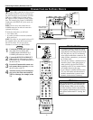
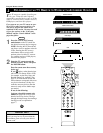
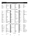
• The HD INPUT-AV 4 jacks are for standard RCA connectors. Your HD
receiver may use RCA or BNC output jacks. If your HD receiver comes
with BNC jacks, you will need to purchase BNC-to-RCA adapters to
connect the receiver to the TV. You should be able to purchase these
adapters at stores that sell electronics. Or you can call our Customer
Care Center at 1-800-531-0039.
• The HD INPUT-AV 4 jacks are compatible with some digital equipment
having RGB outputs with “sync on green” or RGB with “separate H and V
sync.” Output standards for digital equipment, however, may vary by manu-
facturer. No industry standards have been established for HD television RGB
signal systems, timing, synchronization, and signal strengths. If the digital
equipment you want to connect to your TV offers both component video and
RGB outputs, component video is the suggested connection to use.
• The default color-space setting for the HD INPUT-AV 4 jacks is YPbPr.
RGB is also an option. If the picture’s color looks grossly incorrect, try
changing either the HD receiver’s or TV’s color-space setting. See the
receiver’s directions-for-use manual for information on setting its color
space. Or see page 56 in this manual for setting the TV’s color space.
• The Picture-in-Picture feature does not function with the
HD INPUT-AV
4
signal source. AV4 cannot be accessed in the PIP window, nor can the
PIP window be accessed when AV4 is being viewed on the main screen.
HELPFUL HINTS
BNC-to-
RCA
Adapter
BNC
Connector
Adapter
Fitted to
Connection
OR
RCA
Connector