


8
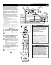
CONNECTING A VCR
AND CABLE BOX
L
L
Rear of TV
Coaxial Cable Lead-in from
Cable TV Company
3
Rear of VCR*
5
6
4
Rear of Cable Box
Two-way
Signal
Splitter
2
1
P
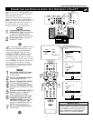
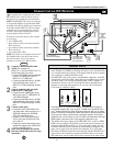
resented here is a connection example
involving a VCR and cable box.
Refer to the VCR’s directions-for-use manual
for further information on connections.
To make the connections in this example, you
will need:
• one, two-way signal splitter
• two coaxial cables (75Ω)
• one cable for a video connection (standard
RCA connector)
• two cables for audio connections (standard
RCA connectors) (only one cable is needed
for connection to a nonstereo VCR).
NOTE: The cables are not supplied with your
TV. You should be able to buy them at most
stores that sell electronics. Or you can call
our Customer Care Center at 1-800-531-0039.
1
Connect a cable TV signal to a two-
way signal splitter.
2
Connect one of the two-way signal
splitter outputs to the INPUT on the
cable box.
3
Connect the other two-way signal
splitter output to the ANTENNA IN
75Ω on the rear of the TV.
4
Connect from the cable box OUT-
PUT jack to the ANT IN jack on the
rear of the VCR.
5
Connect the VIDEO OUT jack on
the VCR to the INPUT-AV 1 VIDEO
jack on the rear of the TV.
6
Connect the AUDIO OUT R(ight)
and L(eft) jacks on the VCR to
INPUT-AV 1 AUDIO jacks on the rear
of the TV.
NOTE: If the VCR is a nonstereo unit,
connect only the left audio cable,
which usually has a white connector.
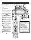
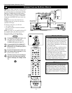
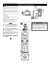
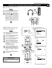
7
Press the AV button on the remote
control as many times as necessary
to select the AV1 source.
8
Turn the VCR on and push PLAY to
view a videotape.
Connecting Accessory Devices to Your TV
BEGIN
PIP ON/OFF
213
546
879
0
TV
SWAP PIP CH
DN
UP
ACTIVE
CONTROL
FREEZE
SOUND
MUTE
SURF
A/CH
POWER
PICTURE
STATUS/
EXIT
SURF
ITR/
RECORD
HOME
VIDEO
HOME
MOVIES
PERSONAL
SLEEP
REC •
PIPPOSITION
VCR
ACC
MENU/
SELECT
VOL
CH
TV/VCR
FORMAT
SAP
PROG.LISTDOLBY VAV
7
AV1
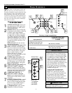
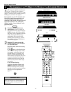
To simplify making connections, the con-
nectors on audio and video cables are often
color coded. The jacks on your TV are like-
wise color coded to match the connectors.
The coding is as follows:
• Yellow for video (composite)
• Red for the right audio channel
• White for the left audio channel
NOTE: If your VCR is mono (non-
stereo), you will connect only one audio
cable. You must ensure that the TV is set
to MONO for the signal source to which
you’ve connected the VCR (
INPUT-AV
1,
INPUT-AV2, or the side panel inputs
[AV3]). Otherwise, you will receive
sound from only one of the TV’s speak-
ers. See page 34.
HELPFUL HINT