


12 Hookups (cont’d)
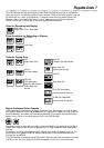
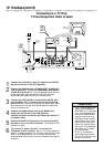
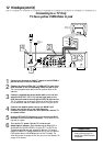
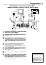
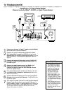
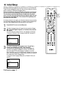
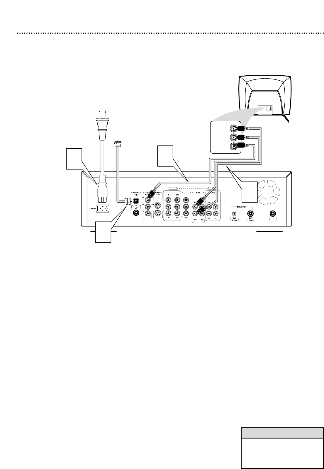
Connecting to a TV Only
TV has a yellow CVBS Video In jack
COMPONENT VIDEO PROG
SCAN
EXT 2
YY
P
B
P
B
P
R
Y
L
LL
R
RR
P
B
P
R
P
R
EXT 3 EXT 3
EXT 1 EXT 1/2
IN
RC 6
Back of TV
(example only)
2
LEFT AUDIO IN
RIGHT AUDIO IN
LEFT AUDIO IN
RIGHT AUDIO IN
3
VIDEO IN
VIDEO IN
4
Antenna
or Cable TV
Signal
1
1
Connect your Antenna or Cable TV signal to the ANTENNA
jack on the rear of the DVD Recorder.
2
Connect the yellow VIDEO OUT (CVBS) (EXT 2) jack of the
DVD Recorder to the corresponding VIDEO IN jack on your
TV. Use the supplied video cable, which has a yellow stripe on the
cable end.
3
Connect a supplied two-strand audio cable to the red and
white AUDIO OUT (EXT 1/2) left and right jacks on the
DVD Recorder and to the left/right AUDIO IN jacks on the
TV. The supplied two-strand audio cable has red and white stripes
on the cable ends. Match the cable stripe colors to the jack colors.
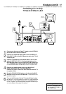
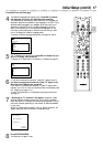
4
Connect the supplied power cord to the MAINS (AC
Power) jack on the rear of the DVD Recorder.
Connect the power cords of the DVD Recorder and the TV
to a power outlet.
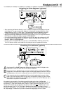
5
Press the STAND BY/ON button on the front of the DVD
Recorder to turn on the DVD Recorder. The STAND BY/ON
light will turn green.
6
Turn on the TV power. Set the TV to the correct
Audio/Video In channel. Such channels may be called AUX or
AUXILIARY IN, AUDIO/VIDEO or A/V IN, EXT1 or EXT2, etc.
These channels often are near channel 00. See your TV owner’s
manual for details. Or, change channels at the TV until you see the
DVD screen saver or Initial Setup menu on the TV screen.
The
Initial Setup screen will appear the first time you turn on the Recorder. Go
to page 16 to continue.
• On the TV, the Video In jack is
usually yellow and might be
labeled video, CVBS, composite,
or baseband.
Helpful Hint