Digital Video Recorder User Guide
20
Digital Video Recorder User Guide
21
Basic Connection Diagram
Connecting Cameras
Chapter 3. Hardware Installation
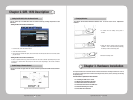
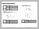
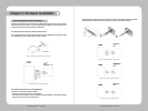
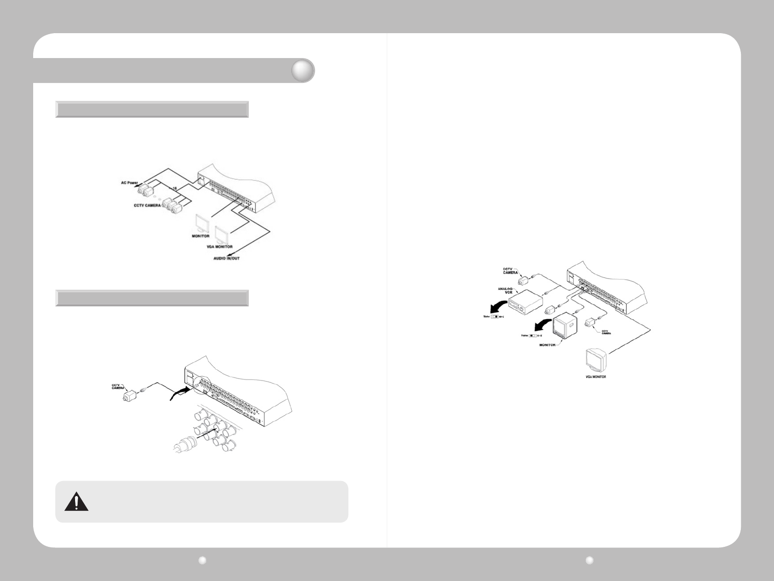
Thefollowingcongurationdiagramdepictsabasicsamplecongurationthatincludecameras,
monitors, sensors, and relays. These diagrams are representative only and are not intended to
depicttheonlypossiblecongurationsfortheSVR-1670.
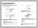
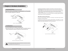
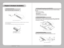
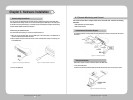
1.EnsurethattheSVR-1670isnotconnectedtoalivepowersource.
2.Using videocable, connectup to16 standardCCTV camerasto theSVR-1670. Followthe
instructionsprovidedwiththecamerastoconnectthemtoanexternalpowersource.
Figure 3.3.1 Sample Connection Diagrams
Figure 3.3.2 Connecting Cameras to the SVR-1670
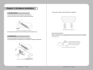
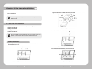
Figure 3.3.3 Video Input and Output Connections
Never connect both NTSC and PAL cameras to the SVR-1670 at the same time. The SVR-
1670 recognizes only one camera type at a time.
ThefollowingdefaultsettingsareassignedtocamerasthatareconnectedtotheSVR-1670.
·
Video input type, which is determined by the device that is connected to the lowest channel number. For
example, if there are five cameras connected to the SVR-1670 and the lowest channel number in use is
6, then the SVR-1670 will set the video input type to match the camera connected to channel 6.
· Terminal resistance, which the SVR-1670 automatically sets at 75Ω when one video input port is in
use. When a lower video input port is also connected, the SVR-1670 automatically separates the terminal
resistance between 75Ω and Hi-Z (high impedance).
About Video In and Out Connections
The SVR-1670 video input/output connections are “Loop through." Their connection status is detected
automatically to set terminal resistance.
For example, when only video input is connected, terminal resistance is set internally to 75Ω. When
video input and output are connected, terminal resistance is set to Hi-Z. This setting for input and output
connections sets the external output device to 75Ω for terminal resistance.


