Digital Video Recorder User Guide
26
Digital Video Recorder User Guide
27
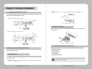
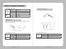
Thesensorspecicationsareasfollows.
Specication
No. of inputs 16 transistor input
Input types N.C, N.O support
Support Sensor Dry contact sensor
Connection method Insert stripped wire end into terminal block
Electric
capacity
Pulse width of usable
input
Minimum 500ms
Output power Typical DC 12mA
Chapter 3. Hardware Installation
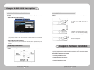
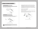
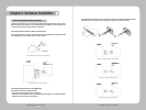
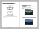
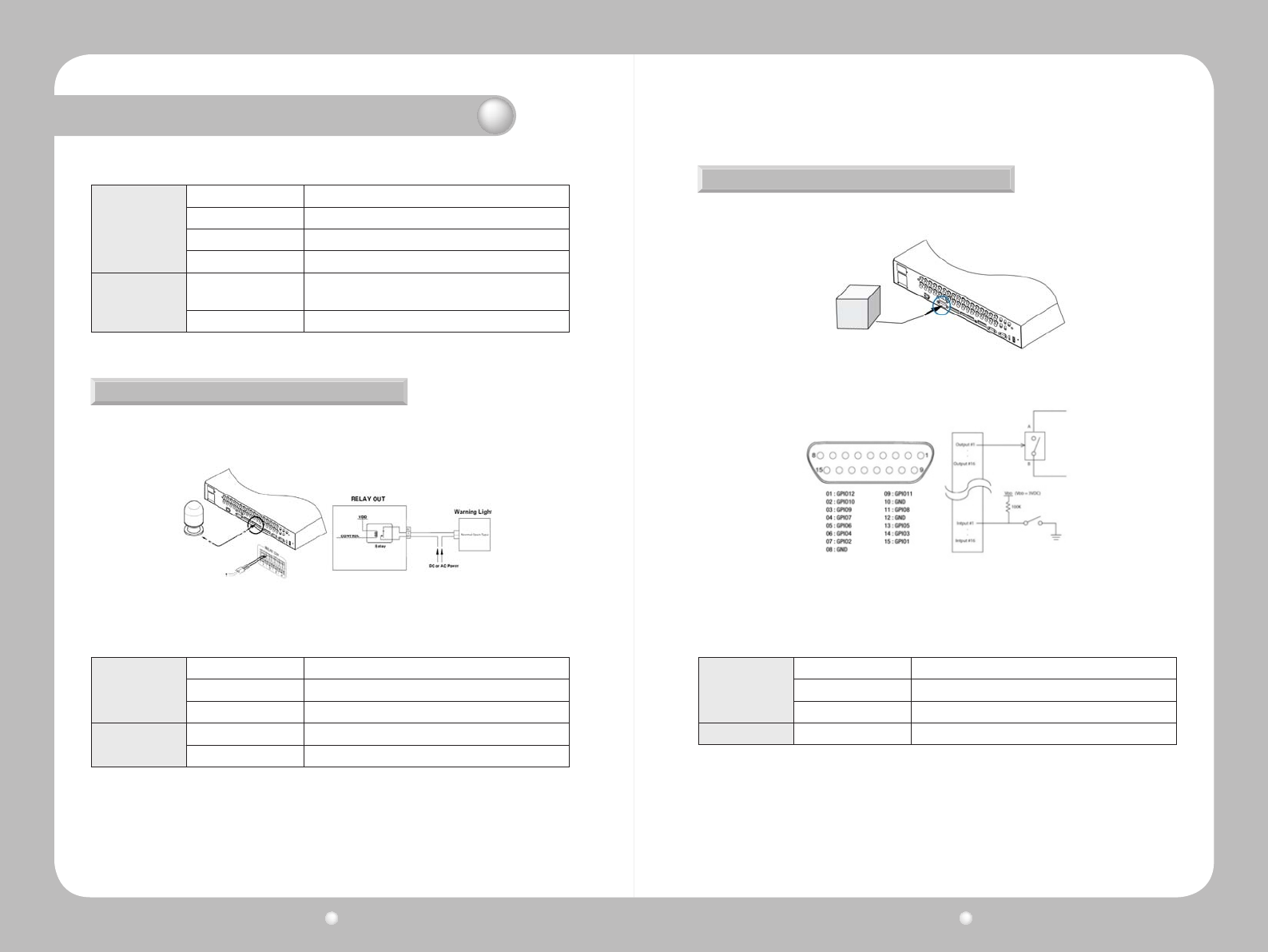
ConnectrelaystoR1throughR4asillustratedinthegurebelow.TheillustrationinFigure3.4.3
shows how to connect a warning light.
Figure 3.4.3 Relay Connections for a Warning Light
Relay Connections
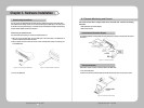
Thealarmspecicationsareasfollows.
Specication
No. of outputs 4 relay outputs
Output type Dry contact
Connection method Insert stripped wire end into terminal block
Rated
current
DC 24V 1A
AC 125V 0.5A
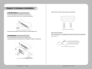
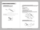
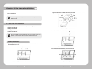
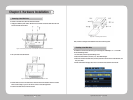
ConnectadigitaldevicetotheD-I/Oinputandoutputterminals.
D-I/O Connections And Settings
Figure 3.4.4 D-I/O device connection
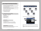
Figure 3.4.5 Digital Input/Output Connections
D-I/O
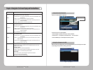
TheD-I/Ospecicationsareasfollows.
Specication
No. of inputs/outputs 12
Output type DC 3V output
Connection method Connect stripped wire end with 15 pin D_SUB.
Ratedcurrent DC 3.3 V


