


10
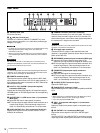
Locations and Functions of Parts
e PANEL ACTIVE button
Activates the control panel to control the camera connected to
the CCU (panel active state). When the button is lit, the
IRIS/MB ACTIVE indicator also turns on simultaneously.
When the button is not lit, the panel is deactivated (panel lock
state) to prevent inadvertent operation.
f SW1, SW2 (assignable switch 1, 2) buttons
Controls the function assigned to each button on the <FRONT
PANEL 1> page in the CCU CONFIGURATION menu. The
button light turns on/off as the assigned function is switched
on/off.
See “ASSIGNABLE/CUSTOM” on <FRONT PANEL 1> on
page 27.
g BARS (color bars) button
Switches on the color bar signal output to the monitor
connected to the CCU (button light turns on). Pressing the
button again restores the previous signal output.
h STANDARD button
Stores the current camera settings as the reference file data
values in the camera (button light turns on for a few seconds).
While the button is lit, pressing the button again cancels the
operation and restores the previous data values.
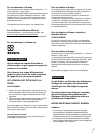
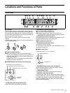
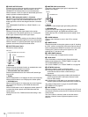
i SHUTTER control block
Controls the shutter settings.
• ON button
Switches the normal shutter function or extended clear scan
function on/off (button light turns on/off).
• ECS (extended clear scan) button
Switches the extended clear scan mode on/off (button light
turns on/off).
•Display
When the ECS button is lit: Displays the clear scan frequency.
When the ECS button is not lit: Displays the shutter speed.
• UP/DOWN lever
When the ECS button is lit: Adjusts the clear scan frequency.
UP increases the frequency, and DOWN decreases the
frequency.
When the ECS button is not lit: Adjusts the shutter speed. UP
increases the shutter speed, and DOWN decreases the
shutter speed.
Holding the lever UP or DOWN advances the setting in that
direction.
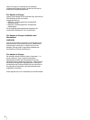
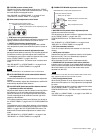
j MASTER GAIN control block
Controls the video output signal gain in response to the
lighting of the subject.
•Display
Displays the video output signal gain setting (dB units).
• UP/DOWN lever
Adjusts the video output signal gain setting (dB units).
UP increases the gain, and DOWN decreases the gain.
Holding the lever UP or DOWN advances the setting in that
direction.
k ALARM indicator
Lights up red to indicate an error in the CCU or camera
system.
l POWER switch
Switches the power for the entire system on and off, including
the CCU, camera, and the RCP-1000-series Remote Control
Panel connected to the REMOTE connector on the rear panel.
Pressing the “?” side turns the camera system on, and
pressing the “a” side turns it off.
m CAM POWER indicator
Turns on when power is supplied to the camera.
n LOCK switch
Locks the buttons on the front panel. Select the desired
buttons to be locked on the <FRONT PANEL 3> page in the
CCU CONFIGURATION menu.
See “(LOCK TARGET)” on <FRONT PANEL 3> on page 29.
o NETWORK indicator
Displays the network system connection status.
On: Indicates that external control equipment (RCP-1000-
series Remote Control Panel or other device) is
connected.
Flashing: Indicates a connection problem with the external
control equipment (RCP-1000-series Remote Control
Panel or other device).
Off: Indicates that a LAN cable is not connected or that the
network system connection parameters have not been set.
See “Network diagnostics” on page 15 and NETWORK
SETTINGS menu on page 29.
p CALL button
Sends a call signal to the camera connected to the CCU and
any external controller (such as the RCP-1000-series Remote
Control Panel).
The CALL button is commonly used to raise the camera
operator or external control equipment operators on the
intercom.
ECS
ON
DOWN
UP
SHUTTER
ON button
ECS (extended clear scan) button
UP/DOWN lever
Display
DOWN
UP
MASTER GAIN
UP/DOWN lever
Display