


24
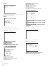
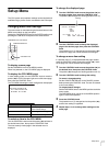
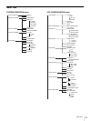
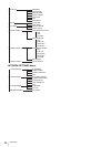
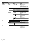
Setup Menu
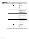
<MONITOR 2>
C04
LEVEL GATE ---, 1&2, 1, 2, OFF 1&2: Displays level gate 1&2
1: Displays level gate 1
2: Displays level gate 2
---: Displayed when camera not connected,
video output not set to CAMERA, or video
output is set to CAMERA and GATE MARKER
is ON (display only)
Y LEVEL1 0 to 108% 49
61 Level gate 1 minimum and maximum detection
levels settings
–99 to 99 –25
Level gate 1 zebra range settings
Y LEVEL2 0 to 108% 74
108 Level gate 2 minimum and maximum detection
levels settings
–99 to 99 –25
Level gate 2 zebra range settings
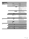
GATE MARKER ---, ON, OFF
Gate signal display on/off settings
---: Displayed when camera not connected
(display only)
–99 to 99 0
Gate signal level settings
MODULATION ---, ON, OFF
4:3 aspect ratio mask function on/off settings
when EDGE CROP is ON
---: Displayed when camera not connected
(display only)
–99 to 99 0
Mask video level settings
MARKER ON, OFF
Marker signal on/off settings
4:3
, 13:9, 14:9, EU VISTA, VISTA,
CINEMA, FOLLOW DC
Superimposed marker signal selection
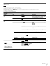
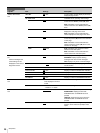
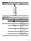
<MIC/AUDIO>
C05
CAM MIC GAIN Microphone gain settings
CH1 ---, 20, 30, 40, 50, 60
dB Settings vary depending on microphones
---: Displayed when camera not connected
(display only)
CH2 ---, 20, 30, 40, 50, 60
dB
AUDIO OUTPUT Audio output level settings
CH1 LEVEL –20, 0
, +4 dBu CH1 output level settings
CH2 LEVEL –20, 0
, +4 dBu CH2 output level settings
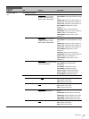
<INTERCOM>
C06
SYSTEM I/F 4WIRE
, RTS, CLEAR COM Intercom interface (D-sub 25-pin) settings
TERMINATION (OFF
), ON, OFF Connects to a 200 Ω terminator, if ON is
selected while 2-wire intercom interface (RTS
or CLEAR COM) is used
(OFF): Displayed when 4WIRE is selected in
SYSTEM I/F (display only)
PGM INPUT –20, 0
, +4 dBu PGM input level settings
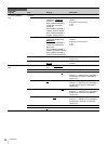
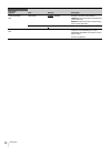
CCU CONFIGURATION
Page name
Page No.
Item Settings Description