


12
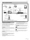
Locations and Functions of Parts
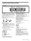
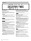
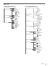
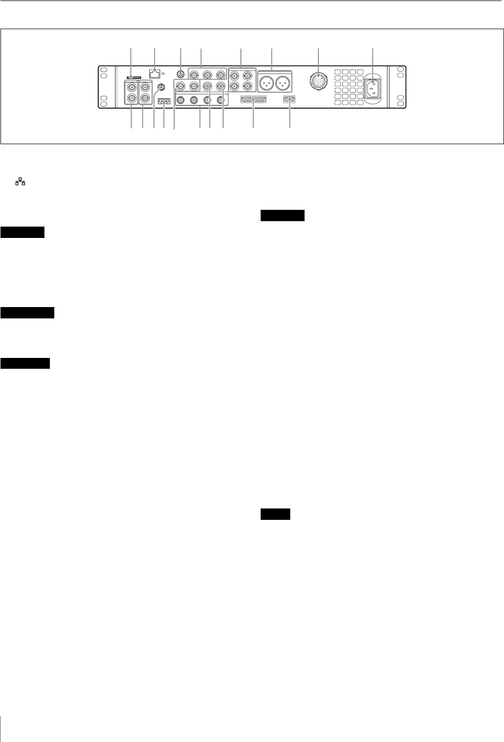
Rear Panel
a “Memory Stick” slot
For service use only.
b LAN jack (RJ-45, 8-pin)
Connects to a LAN hub (10BASE-T/100BASE-TX), when
using a network connection, via a LAN cable (shielded type,
category 5 or higher).
• For safety, do not connect the connector for peripheral device wiring
that might have excessive voltage to this port. Follow the
instructions for this port.
• When you connect the LAN cable of the unit to peripheral device,
use a shielded-type cable to prevent malfunction due to radiation
noise.
Par mesure de sécurité, ne raccordez pas le connecteur pour le
câblage de périphériques pouvant avoir une tension excessive à ce
port. Suivez les instructions pour ce port.
Aus Sicherheitsgründen nicht mit einem Peripheriegerät-Anschluss
verbinden, der zu starke Spannung für diese Buchse haben könnte.
Folgen Sie den Anweisungen für diese Buchse.
c REMOTE connector (8-pin)
Transmits and receives control signals from the RCP-1000-
series Remote Control Panel via a CCA-5 cable (optional). It
also supplies power when connected to an RCP-1000-series
Remote Control Panel.
d Pr/R/R-Y, Y/G/Y, Pb/B/B-Y (component signals)
connectors (BNC type)
Outputs the HD component signals, SD component signals,
HD RGB signals, or SD RGB signals from the corresponding
connectors.
e VBS RETURN 1, 2 (VBS return video 1, 2) connectors
(BNC type)
IN: Inputs the VBS return video signals (2-system).
OUT: The input signal is output from the other connector as-is
(loop-through output). If the loop-through output is not
used, it is automatically connected to a 75 Ω terminator.
f AUDIO OUTPUT CH-1, CH-2 connectors (XLR 3-pin)
Outputs audio signals from the camera AUDIO 1 IN and
AUDIO 2 IN connectors.
g CAMERA connector (multi-core connector)
Connects to the camera via a multi-core cable. The camera
sends all video and audio signals to the CCU, and the CCU
sends control signals, return video, audio signals and power to
the camera over a single multi-core cable.
CAMERA connector is non LPS (Limited Power Source) circuit. This
connector is connected to the HXC-D70.
h AC supply input connector
Connects to the AC supply via the specified power cord
(optional). A plug holder (optional) can be used to secure the
power cord to the CCU.
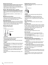
i REFERENCE (reference input) connectors (BNC type)
IN: Inputs an HD tri-level reference sync signal or SD
reference sync signal (black burst signal) for external sync.
OUT: The input signal is output from the other connector as-is
(loop-through output). If the loop-through output is not
used, it is automatically connected to a 75 Ω terminator.
j PROMPTER (teleprompter input) connectors
(BNC type)
IN: Inputs the VBS signal for the teleprompter.
OUT: The input signal is output from the other connector as-is
(loop-through output). If the loop-through output is not
used, it is automatically connected to a 75 Ω terminator.
k S-VIDEO OUTPUT connector (4-pin)
Outputs S-VIDEO signal.
l HDMI OUTPUT connector (19-pin)
Outputs HDMI signal for a video monitor compatible with HDMI
input.
• When connecting a household television with HDMI input, set its
high-resolution function to off to avoid image artifacts.
• Use a Sony high-speed HDMI cable.
m VBS 1, 2 (composite video signal 1, 2) connectors
(BNC type)
Outputs (2-system) the camera signals in composite signal
format.
n SDI OUTPUT 1 to 4 connectors (BNC type)
Outputs the camera signals in HD SDI or SD SDI signal
format.
The SDI OUTPUT 3 and SDI OUTPUT 4 connectors can also
output signals with superimposed character or marker display.
SDI OUTPUT
REFERENCE PROMPTER
S-VIDEO
OUTPUT
HDMI
OUTPUT
SYNCPIXVBS2VBS1
Pb/B/B-YY/G/YPr/R/R-YREMOTE
AUDIO OUTPUT
INTERCOM/TALLY/PGM
TRUNK
VBS RETURN
CH-1
1
1234
2
IN IN
OUT OUT
CH-2
IN IN
OUT OUT
PRO
CAMERA
~ AC IN
a
i
j
m
l
k
n
o
p
q
r
b
c
d
e
f
h
g
CAUTION
ATTENTION
VORSICHT
CAUTION
Notes