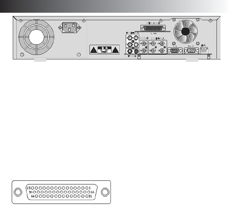
BACK PANEL ...continued
Back Panel and connection outlet:
1 Ventilation fan
2 AC220V power in
3 Power switch
4 Alert signal in/out/ RS-485: 4 channels input/ output
5 Audio input: provide 4 channels audio input
6 Audio output: 2 channels for audio out, left side for replay output, right side for
the surveillance output
7 Video output: 2 channels for video signal output, channel 1 for surveillance output,
channel 2 for mixed video output
8 Video input: Channel 1~4 for video signal input
9 VGA: output with external computer monitor, only for Playback screen or on time recording screen,
not for surveillance review
Method: Press[F2]in remote control after key in password,
then switch the screen from display output with monitor screen
10 RS-232: Standard RS-232 connection
11 Ventilation fan for main unit
MPEG4 Alarm connector pin definition:
Pin definition:
PIN DEF FUNCTION PIN DEF FUNCTION
1 IN0 . . . . . . . .Channel 1 Alarm input 16 . . . .4COM . . . . . .Channel 2 Alarm output
2 IN1 . . . . . . . .Channel 2 Alarm input 17 . . . .4NO
3 IN2 . . . . . . . .Channel 3 Alarm input 18 . . . .4NC
4 IN3 . . . . . . . .Channel 4 Alarm input 19 . . . .COM
5 IN4 . . . . . . . .NC 20 . . . .NO
6 IN5 . . . . . . . .NC 21 . . . .NC . . . . . . . . .Power fault report output
7 IN6 . . . . . . . .NC 22 . . . .COM
8 IN7 . . . . . . . .NC 23 . . . .NO
9 OUT0 . . . . . .Channel 3 Alarm output 24 . . . .NC . . . . . . . . .Fault report output
10 OUT1 . . . . . .Channel 4 Alarm output 25 . . . .485A . . . . . . .485A
11 OUT2 26 . . . .485B . . . . . . . .485B
12 OUT3 27-38 . .GND . . . . . . . .Ground
13 3COM . . . . .Channel 1 Alarm output 39-44 . .+12V . . . . . . .+12V
14 3NO
15 3NC
2, 4 channels alert layout definition
1-2 channels for open socket switch output, no need for additional alarm driver.
3-4 channels for power levels output(OUT for low power out), require additional alarm drive add in here.


