


31
ELECTRIC CIRCUIT EXPLANATION
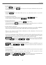
2. DMD Driver PCB
The processed digital signal is sent from the RGB/Control PCB to the DMD Driver PCB via
the 96-pin digital signal cable. The TI driver IC controls to signal supplied to the DMD
through frame memory buffers.
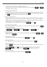
3.
Power Supply PCB
The power supply consists of two sections, Power Factor Control and DC-DC conversion.
Incoming AC is rectified and supplied to the PFC converter where the resulting power factor
is 1.
The output of the PFC circuit is 370V DC and this is supplied to the main and standby
DC-DC converters and also the Lamp Ballast.
The outputs of the main DC-DC converter are +12V and +4V, the outputs of the standby
DC-DC converter are +12V and +5V.
Over-voltage protection is triggered when the +4V supply rises above +6.3V. SCR201 is
controlled by ZD201 and this triggers the protection circuit.
Short circuit protection of the +12V and +4V lines is monitored by IC101 pin3 and the +12V
and +5V standby lines are monitored by IC104 pin5
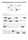
4. Lamp Ballast PCB
The Philips® 120W UHP lamp is driven by Philips ballast power supply, input voltage is
370V DC and high voltage trigger and lamp supplies are output.
5.
RS232C Control PCB
RS232C control signals and remote control from optional CT90000 are accepted, if both are
connected CT90000 has priority.
6.
Video PCB
Accepts PAL/NTSC composite video signal and has a buffered output for loop-through.