


30
Electronic Circuit Explanation
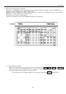
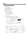
1. RGB/Control PCB
Input signals RGB1 and RGB2 are switched by analogue RGB switch IC, ADG774.
VIDEO input is decoded by VPC3230D, auto-switching between PAL and NTSC, the
output is 16 bit 4:2:2 YUV.
DIGITAL signal is supplied to SII151, single link DVI receiver.
Analogue signals are then converted to digital by A-D converter is AD9884.
The digital signal is supplied to the frequency converter scaler PW164.
The functions of PW164 scaler IC are:
- Auto-detect 48-bit RGB signal display timing
- Auto-adjust capture, position, signal clock and phase
- Auto-capture video 16 bit YUV signal
- Image scaling up/down (VGA, SVGA, SXGA to XGA)
- Frame rate conversion with frame buffer memory
- Video YUV color space conversion
- Test pattern OSD generation
- On-chip 16 bit MPU for software development
- DMD control signal generation
- Digital 24 bit RGB, XGA outputs
Incoming signals are all converted to XGA, 60Hz
Signal recognition and scaling is carried out using standard VESA signals, if a
non-standard signal is supplied the image may not be displayed correctly.
All incoming signals are converted to 60Hz and the color filter rotation speed is 120Hz.
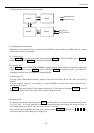
The output from the scaler is supplied to the magnification scaler, GmZ4S and this IC is
controlled by MCU8051.