


2
CONTENTS
SAFETY PRECAUTIONS FOR USER 3
PRECAUTIONS FOR USE AND MAINTENANCE 7
GENERAL DESCRIPTIONS 8
1. FEATURES 8
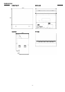
2. DIMENSIONS 9
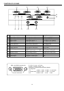
3. PART NAMES AND FUNCTIONS 10
3-1. I/O PANEL 10
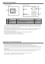
3-2. POWER PANEL 11
4. POWER SWITCH AND POWER INDICATOR 11
5. SPECIFICATIONS 12
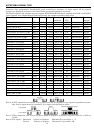
6. ACCEPTABLE SIGNAL TYPE 13
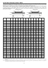
7. ACCEPTABLE RGB INPUT SIGNAL TIMING 14
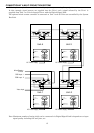
8. CONNECTION AT A MULTI-PROJECTION SYSTEM 15
DISASSEMBLY 16
1. HOW TO REPLACE THE LAMP 16
2.
LOCATION OF KEY COMPONENTS AND FUNCTION MODULE
18
3. EXPLODED VIEW OF THE PROJECTION BLOCK 19
5-1. Removing the DLP engine 20
5-2. Installing the DLP engine 20
4.
EXPLODED VIEW OF THE SCREEN BLOCK AND CABINET
21
5. WIRING 22
ADJUSTMENT 23
1. ADJUSTING THE DLP ENGINE 23
2. ADJUSTING THE ENGINE MOUNT 24
3. ELECTRONICS ADJUSTMENT OR SETTING 26
3-1. Input Signal selection 26
3-2. Adjust Mode 27
3-3. Saving adjustments 27
3-4. Adjustment parameters 27
3-5. Internal Test Pattern 27
3-6. White Balance adjustment 27
3-7. Gain and Off-Set 27
3-8. Clock frequency adjustment and phase adjustment 28
3-9. Image position adjustment 28
3-10. Screen Mode Selection 28
3-11. On-Screen-Display, OSD 28
3-12. Video Enhancer 28
3-13. Interpolation Filter 28
3-14. Image direction 28
3-15. Status Indication 28
3-16. Power ON delay 28
4. Multiple Screen Wall system (example) 29
5. ID Assignment (example) 29
5-1. Clearing I.D. 29
5-2. Setting I.D. 29
5-3. Selecting I.D. 29
6. Magnification 29
Electric Circuit Explanation 30
1. RGB/Control PCB 30
2. DMD Driver PCB 31
3. Power Supply PCB 31
4. Lamp Ballast PCB 31
5. RS232C Control PCB 31
6. Video PCB 31
APPENDIX
1. P600DL control board LED status 32
2. Control via RS-232C -Command Protocol List 33
3. DMD Driver board debug 37
4. PARTS LIST 42
SERVICING DIAGRAM
1. DMD Driver Board Block Diagram 44
2. Signal Process Section Block Diagram 45
3. Wiring Diagram 46
4. ENTIRE BLOCK DIAGRAM 47
5. DMD Board Micro controller 48
6. DMD Display Controller 49
7. DMD Data Formatter 50
8. DMD Memory 51
9. DMD Switching Voltage 52
10. DMD Positive Bias 53
11. DMD Reset ASIC Driver 54
12. DMD Imager 55
13. Motor Rotation Sensor 56
14. Video Input Buffer 57
15. RS-232C Board 58
16. PFC & Main Power Supply 59
17. Sub Power Supply 60
18. Video Decoder 61
19. Voltage Regulator and Fan Control 62
20. 96-pin Connector & D/A Converter 63
21. Magnification Scaler 64
22. MAG/Freq Conv Control MPU 65
23. Freq Conv Scaler 66
24. Freq Conv Scaler 67
25. Analog SW & A/D Converter 68
26. DVI Input Buffer 69
27. DVI Output Buffer 70