


Acutime 2000 Synchronization Kit User Guide 2-3
2 Getting Started
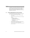
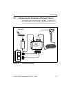
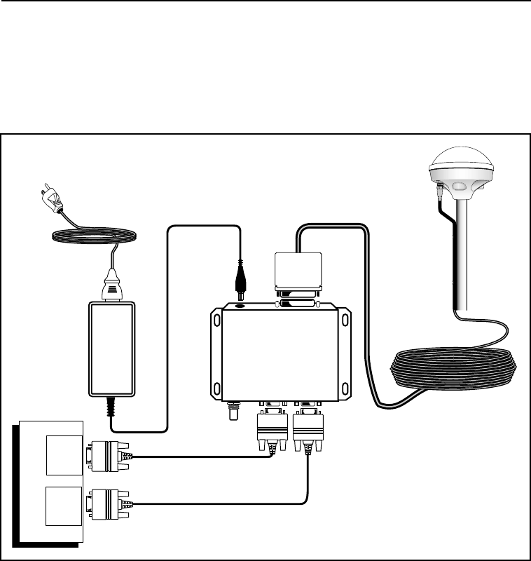
2.2 Connecting the Computer and Power Source
The connection instructions illustrated in Figure 2-1 assume use of
the Trimble interface cable included in the Synchronization Kit. If
you are using your own cable, modify the instructions accordingly.
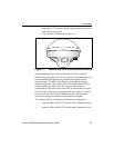
Figure 2-1 Connection Diagram
Synchronization
Interface
Module
Wall Power
Acutime 2000
PPS Port A Port B
Port A
PC
Port B
(primary port)
(RS-422 to RS-232
converter)
(The starter kit includes only one cable.)