


4-6 Acutime 2000 Synchronization Kit User Guide
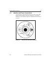
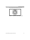
Acutime 2000 Connections
4
!
Note – The cable color codes listed in this table apply only if you are
using the Trimble interface cable.
!
Note – Receive and Transmit are with respect to the Acutime 2000
GPS smart antenna. The host Transmit should be connected to the
Acutime 2000’s Receive, and vice versa.
!
Note – The Acutime 2000 with an RS-232 interface is designed
especially for short cable runs (usually under 50 feet). For longer
cable runs, an RS-422 interface is recommended.
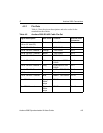
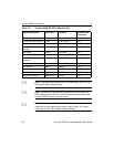
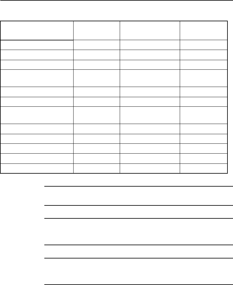
Table 4-3 Acutime 2000 RS-232 Cable Pin-Out
Signal Description Wire Color Protocol Acutime 2000
Connector
DC Power Red +8 to +36V Pin 1
Port B: RS-232 Receive Violet TSIP RS232 Pin 2
Not Used Orange Not Used Pin 3
Port B: RS-232
Transmit
Brown TSIP RS232 Pin 4
Not Used Yellow Not Used Pin 5
Port A: RS-232 Receive White Event Input/RTCM Pin 6
Port A: RS-232
Transmit
Gray TSIP RS232 Pin 7
Vback Green Battery Backup Pin 8
DC Ground Black Ground Pin 9
Not Used Blue Not Used Pin 10
One PPS: Transmit + Orange/White RS422 Pin 11
One PPS: Transmit - Black/White RS422 Pin 12