


ViewSonic VPW505 7
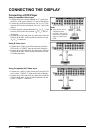
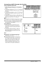
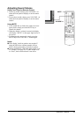
Connecting a HDTV Decoder Set-Top Box
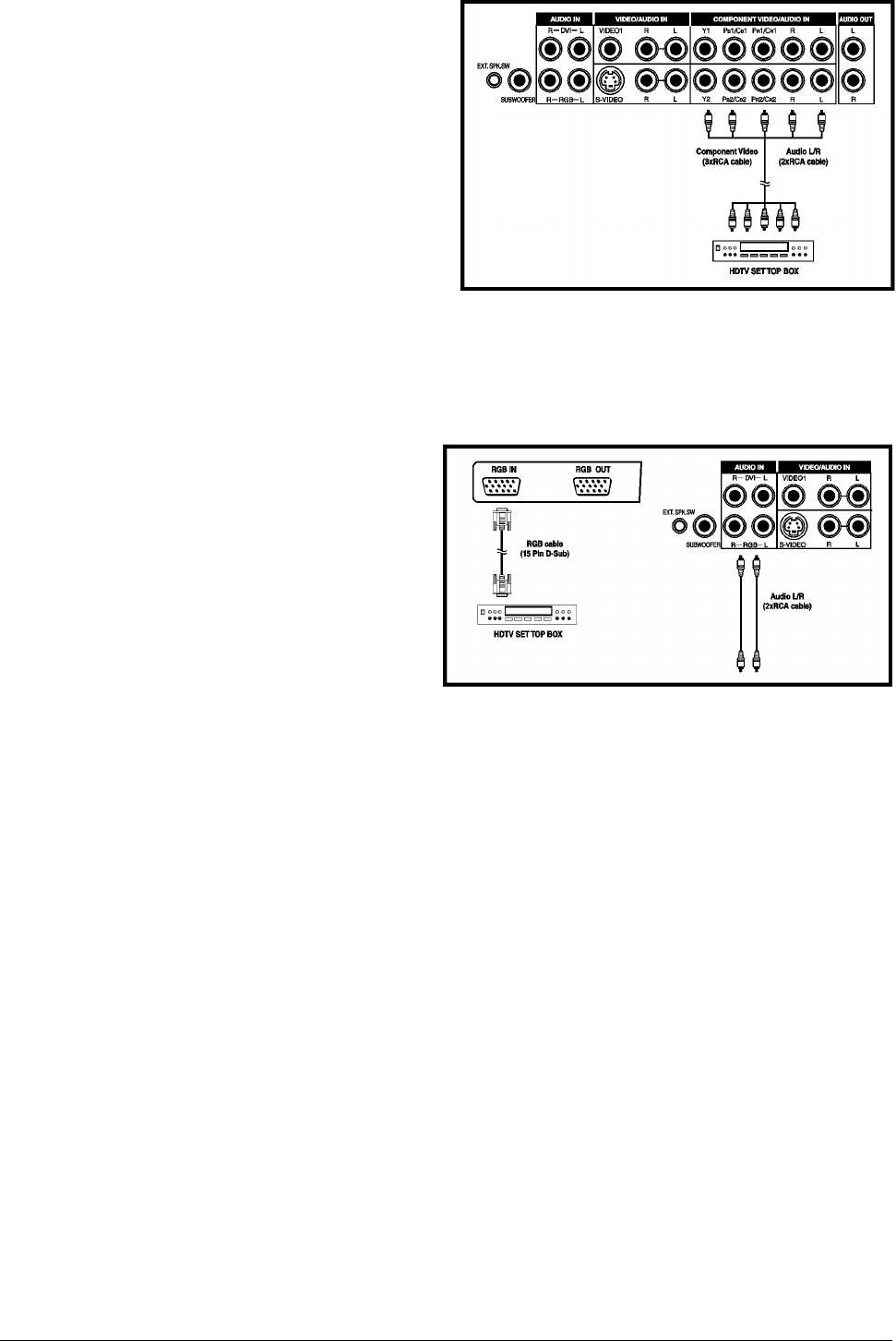
Using Component Video Input
1. Connect the green (labeled as “Y”) jack from the
HDTV Set Top Box to the green “Y1” jack of the
display.
2. Connect the red (labeled as “P
R
” or “C
R
”) jack from
the HDTV Set Top Box to the red “P
R
1/C
R
1” jack of
the display.
3. Connect the blue (labeled as “P
B
”or “C
B
”) jack from
the HDTV Set Top Box to the blue “P
B
1/C
B
1” jack
of the display.
4. Connect the red (R) and white (L) audio jacks from
the HDTV Set Top Box to the R and L audio-in jacks
located next to the “P
R
1/C
R
1” connector.
Note:
Some HDTV Set Top Boxes may not have a Compo-
nent Video output. Instead, use RGB input method.
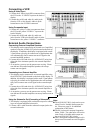
There are two sets of component inputs provided.
You can use either set of component inputs to con-
nect your HDTV Set Top Box.
Using RGB Input
1. Connect the 15-pin D-Sub RGB connector
from the back of the HDTV Set Top Box to
the RGB-IN Connector located on the back of
the display.
2. Connect the red (R) and white (L) audio-out
jacks from the HDTV Set Top Box to the R
and L audio-in jacks located to the left of the
S-Video connector.
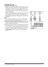
Note:
Some HDTV Set Top Boxes may not have a
RGB output. Use Component Video input
method if this is the case.
Upon connecting your HDTV Set Top Box to
the RGB input of the display, it may be neces-
sary to adjust various picture settings on the
display to correctly match the output of the
HDTV Set Top Box (see page 24). This is
caused by the different video timings set by
various HDTV Set Top Box manufacturers.