Advanced Programming with the VT1529B 165Chapter 5
Field Wiring for
Excitation
Measurements
To take advantage of the on-the-fly excitation measurement feature means
that at least one channel of each VT1529B will need to dedicated to the
excitation voltage measurement. Any of the 32 channels can be used for this
purpose. If the application requires more frequent measurements than once
per scan, multiple channels can be dedicated and a separate excitation
measurement channel for each strain measurement channel can even be
used. The excitation measurement channel must be specified for each strain
measurement channel using SENS:FUNC:STR:<bridge_type>:POST.
For the dedicated excitation measurement channel, simply leave the RJ-45
ports for the channel unconnected. (Putting a short between the strain gage
Sense + and Sense - inputs, however, may be desired. See “Settling Time
Considerations” on page 178 for a discussion of why this may be desired.)
This works because there is an internal 10 kΩ resistor between the Bridge
Excitation input on the front of the VT1529B and the Excitation Sense + and
- inputs for each channel in the 8-channel bank that each Bridge Excitation
input provides power to. Thus, making an excitation voltage measurement
on an unconnected channel input will measure the voltage supplied to the
Bridge Excitation input.
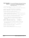
Note For systems with multiple VT1529Bs, the excitation measurements must be
made on the same VT1529B as the strain gage channels that use that
excitation voltage. This means that for a system with two VT1529Bs, the
excitation voltage cannot be measured on only one VT1529B with that
measurement being applied to the strain gage measurements on both
VT1529Bs.
Note The wiring for the strain gage channels is unchanged.
Strain Measurement
Command
Sequence
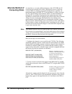
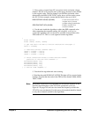
The steps for making strain measurements with the new VT1529B
functionality may already be familiar. The unstrained voltage and gage
factor for the strain channels need to be provided. The excitation channel for
each of the strain channels must also specified as well as the channels to be
scanned. One difference is that the excitation channel(s) must be included in
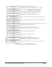
the scan list. Figure 5-1 shows the sequence of VXIplug&play driver calls
to configure and scan strain channels using the new functionality.


