500 Example PID Algorithm Listings Appendix G
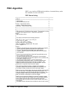
PIDC Algorithm
PIDC is very similar to PIDB with the addition of extended history mode.
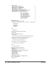
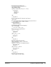
See comments in source code below.
PIDC Source Listing
/********************************************************************************************/
/* PID_C */
/********************************************************************************************/
/* I/O Channels */
/* Must be defined by the user */
/* */
/* inchan - Input channel name */
/* outchan - Output channel name */
/* alarmchan - Alarm channel name */
/* */
/********************************************************************************************/
/* */
/********************************************************************************************/
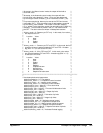
/* PID algorithm for VT1422A controller module. This algorithm is called */
/* once per scan trigger by main(). It performs Proportional, */
Integral */
/* and Derivative control. */
/* */
/* */
/* The output is derived from the following equations: */
/* */
/* PID_out = P_out + I_out + D_out + SD_out */
/* P_out = Error * P_factor */
/* I_out = I_out + (Error * I_factor) */
/* D_out = ((PV_old - PV) * D_factor) */
/* SD_out = (Setpoint - Setpoint_old) * SD_factor */
/* Error = Setpoint - PV */
/* */
/* where: */
/* Setpoint is the desired value of the process variable (user supplied) */
/* PV is the process variable measured on the input channel */
/* PID_out is the algorithm result sent to the output channel */
/* P_factor, I_factor, D_factor and SD_factor are the PID constants */
/* (user supplied) */
/* */
/* Alarms may be generated when either the ProcessVariable or the */
/* error exceeds user supplied limits. */
/* The alarm condition will cause an interrupt to the host computer, */
/* set the (user-specified) alarm channel output to one (1) and set a bit */
/* in the Status variable to one (1). */
/* The interrupt is edge-sensitive. ( It will be asserted only */
/* on the transition into the alarm state.) The alarm channel digital */
/* output will persist for the duration of all alarm conditions. The */
/* Status word bits will also persist for the alarm duration. No user */
/* intervention is required to clear the alarm outputs. */
/* */
/* This version provides for limiting (or clipping) of the Integral, */
/* Derivative, Setpoint Derivative and output to user specified limits. */
/* The Status Variable indicates when terms are being clipped. */
/* */
/* Manual control is activated when the user sets the Man_state variable */
/* to a non-zero value. The output will be held at its last value. The */
/* user can change the output by changing the Man_out variable. User */
/* initiated changes in Man_out will cause the output to slew to the */
/* Man_out value at a rate of Man_inc per scan trigger. */
/* */
/* Manual control causes the Setpoint to continually change to match */
/* the Process Variable and the Integral term to be constantly updated */
/* to the output value such that a return to automatic control will */
/* be bumpless and will use the current Process Variable value as the */
/* new setpoint. */
/* The Status variable indicates when the Manual control mode is active.*/
/* */


