494 Example PID Algorithm Listings Appendix G
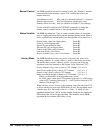
Manual Control The PIDB algorithm provides for manual control with "bumpless" transfer
between manual and automatic control. The variables that control the
manual mode are:
Auto/Manual control; Man_state (0 = automatic (default), 1 = manual)
Manual output control; Man_out (defaults to current auto value)
Manual control slew rate; Man_inc (defaults to 9.99E+37 (fast change))
Use the ALG:SCALAR and ALG:UPDATE commands to change the
manual control variables before or after the algorithm is running.
Status Variable The PIDB algorithm uses 7 bits in a status variable (Status) to record the
state of clipping and alarm limits and the automatic/manual mode. When a
limit is reached or the manual mode is set, the algorithm sets a status bit to 1.
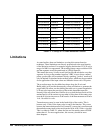
Output (<outp_chan>) at clipping limit; Status.B0
I term (I_out) at clipping limit; Status.B1
D term (D_out) reached at limit; Status.B2
SD term (SD_out) at clipping limit; Status.B3
Control mode (Man_state) is manual; Status.B4
Error term (Error) out of limits; Status.B5
Process Variable (<inp_chan>) out of limits; Status.B6
History Mode The PIDB algorithm provides two modes of reporting the values of its
operating variables. A variable <History_mode> controls the two modes.
The default history mode (<History_mode> = 0) places the following
algorithm values into elements of the Current Value Table (the CVT):
Process Variable (<inp_chan>) value to CVT element (10 * n) + 0
Error Term variable (Error) value to CVT element (10 * n) + 1
Output (<outp_chan>) value to CVT element (10 * n) + 2
Status word bits 0 through 6 (Status) to CVT element (10 * n) + 3
Where n is the number of the algorithm from ’ALGn’.
So ALG1 places values into CVT elements 10 through 13, ALG2 places
values in CVT elements 20 through 23 ... ALG32 places values into CVT
elements 320 through 323.
When <History_mode> is set to 1, the operating values are sent to the CVT
as above and they are sent to the FIFO buffer as well. The algorithm writes
a header entry first. The header value is ( n * 256 ) + 4, where n is the
algorithm number from ’ALGn’ and the number 4 indicates the number of
FIFO entries that follow for this algorithm. This identifies which PIDB
algorithm the five element FIFO entry is from.


