Programming the VT1422A & VT1529A/B for Remote Strain Measurement 73Chapter 3
Connecting to the VT1529A/Bs Dynamic Strain Ports
The VT1529A/B has two, 37-pin connectors that provide wideband
amplified outputs from each strain bridge signal. This allows for connection
to a high-speed ADC-per-channel instrument like the VT1432A or
VT1433B to capture dynamic strain events.
While an instrument like the VT1432A or VT1433B can measure signals
from the VT1529A/B, a VT1422A is still required to control the
VT1529A/B’s bridge configuration, calibration and self-test functions.
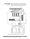
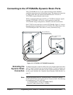
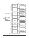
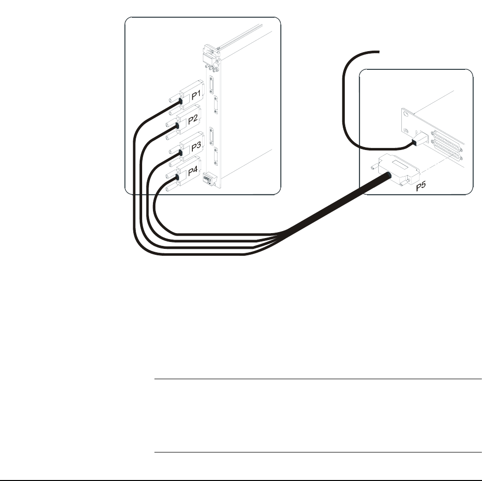
One VT1422A can control up to sixteen VT1529A/Bs. Figure 3-13 shows
the general interconnection layout for a VT1432A. The cable shown is the
VT1529A/B Option 001. This cable is 10 feet (3.05 meters) long.
Extending the
Dynamic Strain
Connection
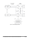
If additional length is required, build or have an extender cable built with a
male, 37-pin D-connector on one end and a female, 37-pin D-connector on
the other. The extender cable must provide sixteen twisted pair conductors
and be overall shielded. See “Dynamic Strain Extender Cable Pin-Out” on
page 74.
Note The spacing between the two "Buffered Output" connectors is narrow
(0.625 in./15.875 mm) and requires narrow connector shells. The following
two manufacturers’ parts work well:
L-COM (distributor catalog Cat# SDRS37HOT)
Cinch DC24660 (Newark Cat# - 45F988)
Figure 3-13. VT1432A to VT1529A/B Connection
16-Channel VT1432A
32-Channel VT1529A/B
VT1422A Provides
Control
Two VT1432As Are
Required to Monitor All
32 VT1529A/B Channels


