VT1529A/B Verification & Calibration 467Appendix C
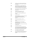
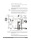
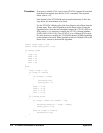
Procedure Set the Voltage Source to +5.000 V. Send the MEAS:VOLT:EXCitation?
(@<ch_list>) command to the VT1422A. The expected measurement value
is approximately +2.5 V on each channel.
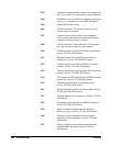
Troubleshooting Failures Check that the Dummy Load is wired and working correctly and firmly
seated in the RJ-45 input connector. If all 8 channels of one block of
VT1529A/B channels are failing, check that the Voltage Source is
connected to the correct terminals on the Bridge Excitation input on the
VT1529A/B.
Test V-4: Bridge
Resistors
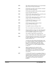
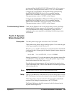
Description This test verifies the operation of the internal bridge completion resistors
and associated switches in the VT1529A/B.
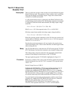
The operation of the internal bridge resistors can be measured by
unbalancing the bridge circuit. The bridge output voltage is a function of the
resistor value as given by the following formula:
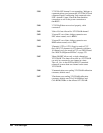
V
sense
= V
excitation
* (10.0 / (10.0 + 7.5 + R) - 0.5)
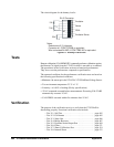
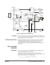
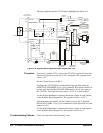
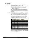
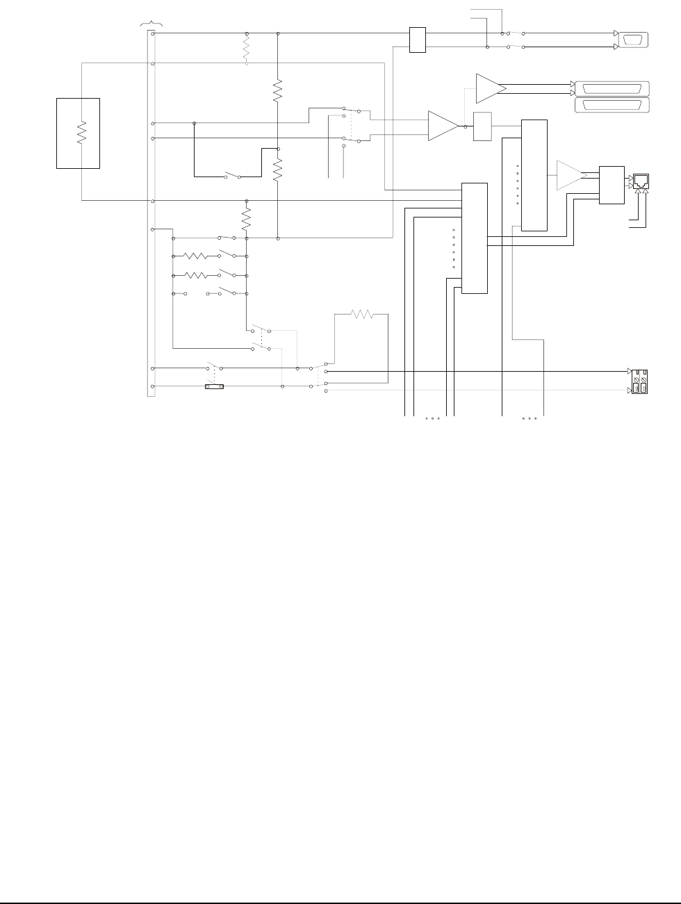
Figure C-2. Signal Path for Sense Out Test
Buffer
To VT1422A
(VT1539A SCP
)
X2
Buffer
RJ-45
X2
2:1
Mux
Cal-
Cal+
8
-p
i
n
T
e
l
com
Connector (RJ-45)
Cal-Cal+
350
120
customer
10K
10K
10K
10K
+
-
Optional
Filter
2,10,100Hz
+Excitation Sense
Instrument.
Amplifier
Dynamic Strain
Output
+ Excitation
- Excitation
Internal
Rcal
50K
Local Rcal
Enable
Remote Rcal
Enable
Int/Ext Rcal
Select
Excitation Sense
fr
o
m
C
H
s
1-
3
1
32:1
Mux
CH31
CH00
CH01
32:1
Mux
CH31
CH01
CH00
Bridge Sense
fr
o
m
C
H
s
1-
3
1
External customer
shunt cal resistor
terminals
-R Cal
+R Cal
Current
Limit
Excitation
to CHs 1-7
enable excitation
CHs 0-7
+Excitation
+Sense
-Sense
-R Cal
+R Cal
+Excitation Sense
-Excitation Sense
-Excitation
Wagner
Voltage enable
off for full bridge
-Excitation Sense
X16
Pin 5
Pin 4
Pin 2
Pin 7
Pin 6
Pin 3
Pin 8
Pin 1
20K
Dummy Load


