


1.2.1 TracVision C3 Components
The antenna unit includes the antenna positioning mechanism,
signal front end, power supply, and control elements. These
elements include antenna drive controls and mechanisms, the
cable wrap subassembly, antenna gyro sensor, power
conditioning and regulating circuits, and the RF detector. The
antenna is a parabolic dish mounting a low noise block (LNB)
converter with built-in preamplifier. The European configuration
includes a single-output LNB while the North American system
uses a dual-output LNB. A molded ABS radome encloses the
fiberglass baseplate and is secured in place with standard
fasteners. Connectors on the back of the baseplate join the power,
signal, and control cabling from below-decks units.
1-3
Introduction
54-0159 Rev. G
The dual-output LNB in the North
American systems allows two
IRD/TV pairs to be connected
directly to the antenna. Three or
more pairs can be connected to the
system if an active multiswitch is
used. Section 2.3.5, “Connecting
the Antenna RF Signal Cable to the
IRD,” provides installation directions
for each of these options.
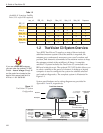
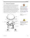
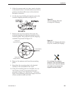
Figure 1-2
Primary Components of the
TracVision C3
Radome
Antenna Unit
Mounting Plate
Antenna
Reflector
LNB Bracket
Gyro
RF PCB
Main PCB
North American LNB European LNB
Always lift the antenna unit by the
gray baseplate and not the radome,
antenna reflector, or internal
mechanical assemblies.
NEVER pick up the unit by the
LNB or the gyro!