


5-8
A Guide to TracVision C3
Antenna Gyro Calibration
1. Connect a PC to the communications port as
described in Section 4.4, “Computer Diagnostics.”
2. Type HALT<cr> (<cr> indicates a carriage return/
ENTER key) while the system is performing the
limit switch initialization routine. The system will
complete the initialization function by finding the
azimuth and elevation switch limits and then go to
the home position.
3. Type DEBUGON<cr> to enter Debug Mode.
4. Type =CALGYRO<cr>. Verify that the Antenna
Gyro Azimuth scale factor is between -0.00090 and
-0.00110 and the Antenna Gyro Elevation scale
factor is between 0.00090 and 0.00110.
5. Type ZAP to restart/reinitialize the system.
5.4.4 Antenna LNB Replacement
Estimated Time to Repair:
1
⁄2 hour
In the event that the LNB experiences problems, it may be
necessary to replace it. To do so, use the following procedure:
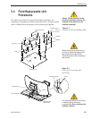
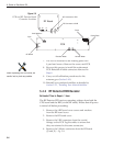
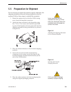
1. (European systems only) Make a note of the current
LNB skew angle, pictured in Figure 5-7.
2. Disconnect the RF cable connector(s) at the LNB.
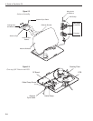
3. Remove the wing nut and washer from the LNB
clamp – Fig. 5-3.
4. Remove the top of the LNB clamp and remove the
LNB.
5. Place the new LNB in the clamp and reattach the
RF connector(s).
6. Replace the LNB clamp:
A. For North American LNBs, tighten the clamp
fully. The replacement process is complete.
B. For European LNBs, do not fully tighten the
clamp and proceed to Step 7.
7. (European systems only) Carefully turn the LNB so
that the scribe mark is aligned with the skew angle
noted in Step 1. Fully tighten the clamp to
complete the replacement process.
The LNB receives power from the
IRD via the RF Detector PCB. Be
certain that the IRD is disconnected
from its power source before
removing or reconnecting the LNB.
Skew Angles
LNB Clamp
& Wing Nut
Scribe
Mark
LNB
Figure 5-7
LNB Skew Angle Setting
(European systems only)