


5-2
A Guide to TracVision C3
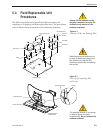
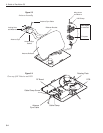
5.3 Replaceable Parts
TracVision C3 has been designed with durability and low
maintenance in mind. If you experience an operating problem or
otherwise require technical assistance, contact your local
authorized TracVision C3 dealer/distributor first. Have the
antenna unit serial number ready with a list of the trouble
symptoms. If an authorized dealer/distributor is not located
nearby, contact the factory directly at the telephone, facsimile, or
e-mail listings inside the front cover.
Replacement part numbers for units that can be serviced in the
field are listed in Table 5-1. These parts may be obtained from
any KVH authorized dealer/distributor.
Part Name Part Number
Baseplate Assembly 02-1245-01*
02-1245-03**
Radome Assembly 02-0953-04
†
Data/Power Cable 32-0730-45
RF Cable 32-0417-45
PC Cable 32-0628-06
CPU PCB 02-1043-02
RF PCB 02-1233
Antenna Gyro 02-1035
Antenna Gyro Gasket 24-0139
System Fuses 16-0017-3150
LNB (European system) 19-0196
LNB (N. American system) 19-0056
Switchplate 02-1023-01
TV/SAT Switch (optional) 01-0245
* Baseplate assembly with single-output LNB
** Baseplate assembly with dual-output LNB
†
Specify color when ordering
It is recommended that all other technical difficulties be resolved
by returning the TracVision C3 unit to an authorized service
provider.
Table 5-1
Field Replaceable Units
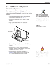
Should a fuse ever need to be
replaced, TracVision C3 uses
two 5x20mm, 3.15-amp, 250-volt
fast-blow fuses.
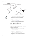
To help us continually improve the
quality and reliability of our
systems, please return any failed
component to KVH or KVH Europe
(care of the mailing address listed
at the front of this manual) after you
receive your replacement part.
The serial number of your
TracVision C3 will be required
during any troubleshooting or
service calls.You will find the
serial number at the front of this
manual.