


2-8
A Guide to TracVision C3
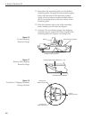
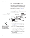
17. Place the radome onto the baseplate (labels facing
the sides of the vessel) and secure in place using
the 8 pan head screws and flat washers removed
in Step 3.
18. Drill the cable access hole (marked in Step 5).
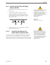
Recommended
3/16" (5 mm)
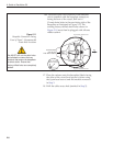
Drain Hole Positions
Drain Hole Angle
(relative to baseplate)
Bow
Angle of Hole, relative to front
Angle of Hole, relative to front
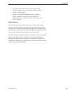
Figure 2-11
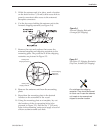
Baseplate Connectors Facing
Front of Vessel – Recommended
Drain Hole Locations
You MUST drill out the drain holes
as indicated to ensure that any
moisture that enters the baseplate
is able to drain. Ensure that
factory-drilled holes are completely
sealed.
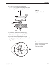
16a. (Alternate Drain Hole Locations) If the antenna
unit is installed with the baseplate connectors
facing the bow of the vessel, drill out
3
⁄16"
(5 mm)-drain holes in the rear-facing side of the
baseplate as illustrated in Figure 2-11. The
existing factory-drilled drain holes shown in
Figure 2-10 must then be plugged with silicone
rubber sealant.