


2-2
A Guide to TracVision C3
Kitpack Contents
Table 2-2 lists the materials provided in the kitpack.
Part Qty. KVH Part No.
Tie-wraps 5 22-0013
1
⁄4"-20 x 3" hex head cap screws 6 14-0250-48
1
⁄4"-20 x
5
⁄8" hex screws 4 14-0250-0010
1
⁄4" flat washers 10 14-0251
Switchplate bulb assembly (spare) 1 19-0193
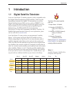
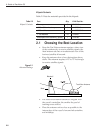
2.1 Choosing the Best Location
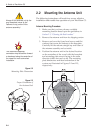
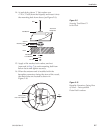
• Since the TracVision antenna requires a clear view
of the southern sky to receive satellite signals, the
ideal antenna site has an unobstructed view of the
horizon/satellite all around.
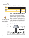
• Keep the antenna clear of any obstructions above
decks. The antenna requires a 15º to 75º look angle
to receive satellite signals.
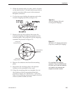
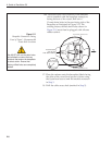
• The closer the antenna reference is aligned with
the vessel’s centerline, the smaller the pool of
tracking errors will be.
• Place the antenna unit as close as possible to the
intersection of the vessel’s fore-and-aft centerline
and midships.
Blocked!
TracVision Antenna
Vessel Platform
Mast
Figure 2-1
Antenna Blockage
Table 2-2
Kitpack Contents