


2-5
Installation
54-0159 Rev. G
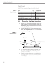
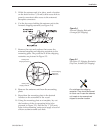
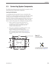
5. While the antenna unit is in place, mark a location
on the deck for the
3
⁄4" (19 mm) cable access hole to
permit convenient cable access to the antenna’s
baseplate connectors.
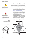
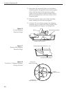
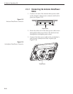
6. Cut the tie-wraps holding the antenna unit to the
forward shipping restraint (see Figure 2-4).
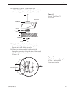
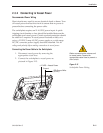
7. Remove the nuts and washers that secure the
antenna baseplate and shipping restraints to the
mounting plate. The positions of all the shipping
restraints are pictured in Figure 2-5.
8. Remove the antenna unit from the mounting
plate.
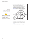
9. Reposition the mounting plate in the desired
location on the centerline of the vessel.
10. Using the mounting plate as a template, lay out
the locations of the six mounting holes (also
pictured in Figure 2-2). Drill the six
3
⁄8" (9.5 mm)
holes in the mounting surface and apply a bead of
silicone sealant around each hole.
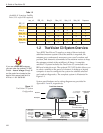
Figure 2-4
Forward Shipping Restraint
(Arranged for Shipping)
Do not discard the shipping
restraints. They should be stowed
for future use in case the antenna
unit needs to be removed and
shipped to another location.
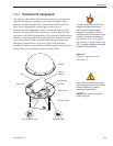
Rotating Plate
Shipping Restraint
Rotating Plate
Shipping Restraint
Forward Shipping
Restraint for
LNB Bracket
Figure 2-5
TracVision C3 Shipping Restraints
(Top View, Installed for Shipping)