


5-5
Maintenance
54-0159 Rev. G
5.4.1 PCB Removal and Replacement
Estimated Time to Repair:
1
⁄2 hour
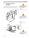
The microprocessor PCB assembly is protected by a cover
fastened to the rotating plate – Fig. 5-1. The cover must be
removed to gain access to the main power fuses and the PCB
assembly.
1. Using needle-nose pliers, remove the E-ring from
one end of the connecting rod – Fig. 5-2.
2. Remove the connecting rod by sliding it off the
bracket.
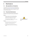
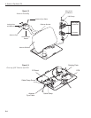
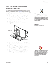
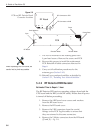
3. Fully retract the elevation axis motor shaft
– Fig. 5-5.
4. Remove the 6 pan head screws from the PCB cover
flanges.
5. Remove the PCB cover. To get the necessary
clearance, rotate the linear actuator up 90º while
lifting the PCB cover – Fig. 5-5.
6. Remove all cable connectors from the PCB.
Figure 5-6 on the following page illustrates the
PCB arrangement and connector locations.
TracVision C3 is equipped with two
5x20 mm, 3.15-amp, 250-volt fast-
blow fuses, which are mounted on
the PCB. To access and replace
one of these fuses, remove the
PCB cover.
When carrying out maintenance
on the PCB, be sure to not drop
any of the small screws inside the
mechanism. If a screw is lost within
the baseplate, it must be retrieved
to avoid causing any damage when
the unit rotates.
PCB Cover
Linear Actuator
Elevation Axis
Motor Shaft
Figure 5-5
Removing the PCB Cover