


10
MULTI-FUNCTION LD CARD
This chapter describes the locations and posssible settings of the Multi-
Function LD Card’s configuration controls, and provides detailed instructions
for setting them. Section 3.1 tells you about the three 8-position DIP switches
on the Card’s main (front) module. Section 3.2 tells you about the three
jumpers (“straps”) on the Card’s interface (rear) module. Once you’ve
configured the Multi-Function LD Card, it is designed to operate
transparently, without needing to be frequently reconfigured. Just set it and
forget it!
3.1 Setting the Switches on the Main Module
3.1.1 W
HERE THE
S
WITCHES
A
RE
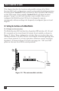
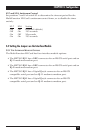
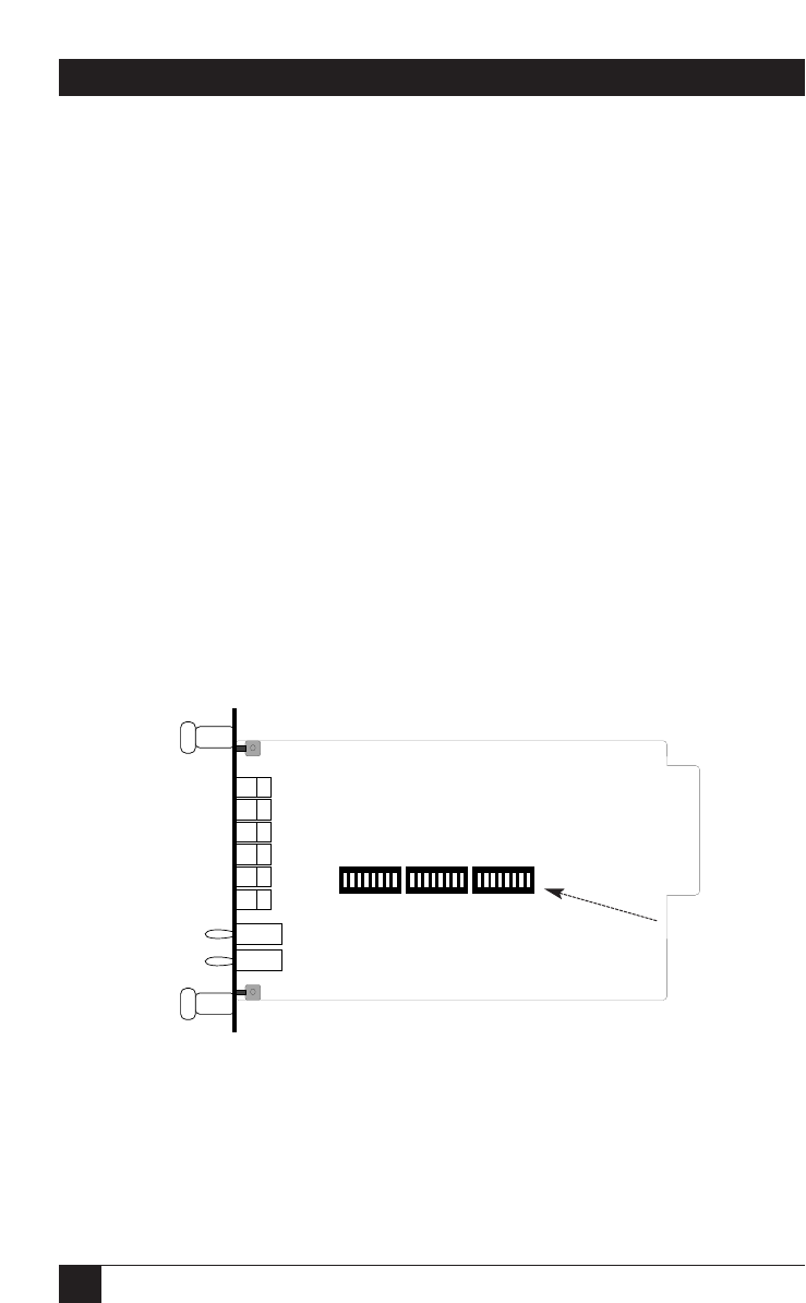
The Multi-Function LD Card has three 8-position DIP switches—S1, S2, and
S3—mounted on the circuit board of its main (front) module, as shown in
Figure 3-1 below. These configuration switches allow you to select data rates,
clocking methods, V.52 and V.54 tests, word lengths, extended signaling rates,
sync or async protocol, 2- or 4-wire operation, antistream control, and input
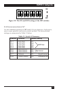
impedance. As shown in Figure 3-2 on the next page, the “ON” and “OFF”
points are the same for all of the switch positions.
Figure 3-1. The main-module switches.
S1 S2
S3
(on other
side of
board)