


20
MULTI-FUNCTION LD CARD
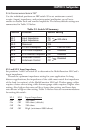
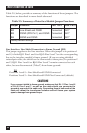
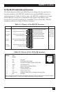
Table 3-5, below, provides a summary of the functions of these jumpers. The
functions are described in more detail afterward.
Table 3-5. Summary of Interface-Module Jumper Functions
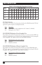
Line Interface: Line Shield Connection to Frame Ground (JB2)
This jumper applies to the line interface. When this jumper is in positions 1
and 2, it links RJ-11 Pins 1 and 6 or RJ-45 Pins 2 and 7 on the corresponding
line to the interface module’s frame ground. (If you are using shielded
twisted-pair cable, the shield can be connected to these pins.) In positions 2
and 3, RJ-11 Pins 1 and 6 or RJ-45 Pins 2 and 7 remain connected to each
other, but are disconnected (“lifted”) from frame ground.
JB2
Positions 1 and 2 = Line Shield and FGND Connected
Positions 2 and 3 = Line Shield and FGND Not Connected (default)
CAUTION!
If you connect shield to frame ground, make sure that RJ-11 Pins 1 and 6
or RJ-45 Pins 2 and 7, as well as the cable shield, are connected to
ground at one end of the cable only. Connecting them at both ends of the
cable will defeat the transformer isolation and will leave your system
open to damage from ground loops.
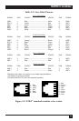
Jumper Function Pos. 1 & 2 Pos. 2 & 3
JB2 Line Shield and FGND Connected N/C*
JB3 PGND (DTE Pin 1) and FGND Connected N/C*
JB4 SGND and FGND Connected N/C*
*factory-default settings