


33
CHAPTER 5: Operation and Diagnostics
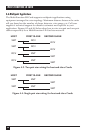
When the local and remote Multi-Function LD Cards are both powered up and
are passing data normally, the LEDs on the Cards will look like this:
• Power: Steadily lit
• TD and RD: Flashing red and green
• RTS and CD: Green steadily lit, red dark
• Test and Error: Dark
5.4 V.54 and V.52 Diagnostic Tests
The Multi-Function LD Card offers two V.54 test modes and two V.52 test
modes to evaluate the condition of the modems and the communication link.
Both sets of tests can be activated physically from the front panel. The V.54
test can also be activated from the RS-232 interface.
NOTE
V.54 and V.52 test modes on the Multi-Function LD Card are available for
point-to-point applications only.
5.4.1 L
OCAL
A
NALOG
L
OOPBACK
(LAL)
The Local Analog Loopback (LAL) test checks the operation of the local
Multi-Function LD Card, and is performed separately on each unit. Any data
sent to the local Multi-Function LD Card in this test mode will be echoed
(returned) back to the user device. For example, characters typed on the
keyboard of a terminal will appear on the terminal’s screen. To perform a
LAL test, follow these steps:
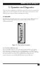
1. Activate LAL. You can do this in either of two ways. One is to move the
upper front-panel toggle switch labeled “Remote—Analog” to the
“Analog” (right-hand) position. The other is to raise the signal on
Pin 18 of the RS-232 interface (switch S3 position 5 must be “On”—see
Section 3.1.4). Once LAL is activated, the Card’s transmit output is
connected to its own receiver. The Test LED should light.
2. Verify that the attached DTE is operating properly and can be used for a
test.
3. Move the lower front-panel toggle switch labeled “511/E—511” to the
“511” (right-hand) position. This will activate the V.52 BERT test mode
and inject a 511 test pattern into the local loop. If any errors are present
in the loop, the Error LED will blink sporadically.