


25
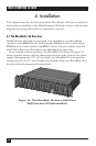
CHAPTER 4: Installation
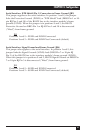
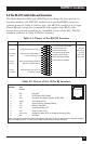
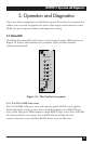
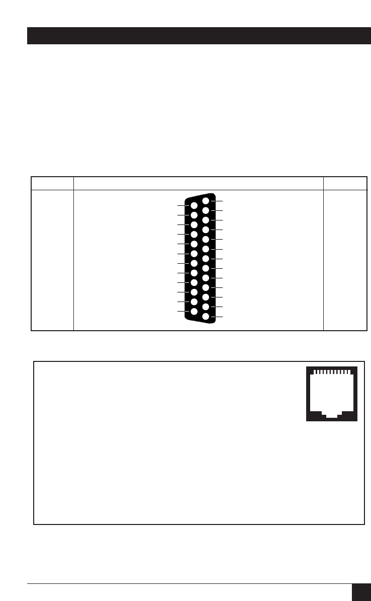
4.4 The RS-232 Serial Cables and Connectors
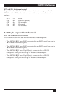
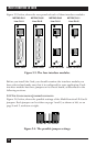
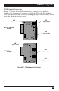
The Multi-Function LD Card’s RS-232 port is always the lower port on its
interface module. On ME758C models it is a standard DB25 connector
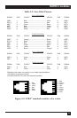
(pinout shown in Table 4-1 below, top). On ME759C models it is a 10-pin
female RJ-style connector (compatible with regular male RJ-45 cable
connectors), pinned according to a modified version of the EIA/TIA-561
standard, as shown in Table 4-2 below (bottom).
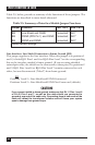
Table 4-1. Pinout of the RS-232 Interface
Table 4-2. Pinout of the 10-Pin RJ Interface
Pin ITU-TSS Signal Name/Description
Number V.24
Circuit
1 N/A Not Used
2 107 DCE Ready (DCR [DSR])
3 109 Received Line Signal Detector (RLSD [CD])
4 108/2 DTE Ready (DTR)
5 102 Signal Common (SCOM [SGND])
6 104 Receive Data (RD)
7 103 Transmitted Data (TD)
8 106 Clear to Send (CTS)
9 105 or 133 Request to Send (RTS) or Ready for Receiving (RR)
10 N/A Not Used
Pins 3 through 9 correspond to Pins 2 through 8 of the EIA/TIA-561 non-synchronous interface standard.
Pin 2 corresponds to Pin 1 of the EIA/TIA TSB-25 preliminary interface standard.
DIRECTION STANDARD RS-232/V.24 DCE PINNING DIRECTION
1 Protective Ground (PGND)
From Card Transmit Clock DCE (TCC) 15
2 Transmit Data (TD) To Card
3 Receive Data (RD) From Card
From Card Receive Clock DCE (RCC) 17
4 Request to Send (RTS) To Card
To Card Local Loopback (LL) 18
5 Clear to Send (CTS) From Card
6 Data Set Ready (DSR) From Card
To Card Data Terminal Ready (DTR) 20
7 Signal Ground (SGND)
To Card Remote Loopback (RL) 21
To Card Transmit Clock DTE (TCT) 24
From Card Test Mode (TM) 25
0 0 0 0 0 0 0 0 0 1
1 2 3 4 5 6 7 8 9 0