


31
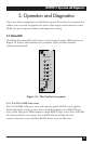
CHAPTER 5: Operation and Diagnostics
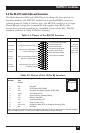
5.2 Diagnostic Testing Using the Error LED
5.2.1 T
ESTING
C
ABLE
Q
UALITY
NOTE
The Error LED’s circuitry is designed to detect line quality across 4-wire
twisted-pair cable only, and might not function properly with 2-wire
cable.
If there is any question as to the quality of your line, we recommend the
following test:
1. Disconnect both local and remote modems from their attached RS-232
DTE devices. Make sure the red TD, RD, and RTS LEDs are all lit.
2. Set the input impedance of both modems to 200 ohms by setting switch
S3 position 1 “On” and S3 position 2 “Off.”
3. Set the data rate on both modems to 9.6 kbps by setting switch S1
position 1 “On,” S1 position 2 “Off,” S1 position 3 “Off,” and S1 position
4 “On.”
4. On the local modem, set carrier control for “Constantly on” by setting
switch S1 position 8 “Off.”
5. On the remote modem, set carrier control to “Controlled by RTS” by
setting switch S1 position 8 to “On.”
6. Move both front-panel toggle switches to the center (neutral) position.
(The Test LED should not light.)
7. Connect both modems to the 4-wire twisted-pair cable to be tested. (See
Section 4.5 for pinouts and guidelines for this type of cable.)
8. Here’s how to interpret the results:
A. If the quality of the line is good, neither modem’s Error LED will
light. The local modem’s red CD LED will light, and the remote
modem’s green CD LED will light.
B. If there is flat satin cable in the line somewhere between the modems,
the local modem’s Error LED and green CD LED will both light. On
the remote modem, the remote modem’s green CD LED will light,
but the Error LED will stay dark.