


18
MULTI-FUNCTION LD CARD
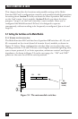
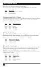
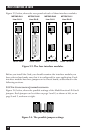
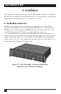
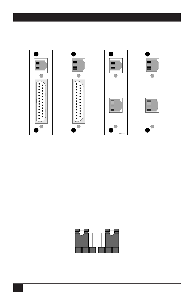
Figure 3-3, below, shows the rear panels of each of these interface modules.
Before you install the Card, you should examine the interface module you
have selected and make sure that it is configured for your application. Each
interface module has three jumpers on its circuit board, as described in the
following sections.
3.2.2 T
HE
C
ONFIGURATION
J
UMPERS
I
LLUSTRATED
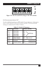
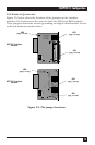
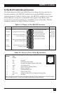
Figure 3-4, below, shows the possible settings of the Multi-Function LD Card’s
jumpers. Each jumper can be either on pegs 1 and 2, as shown at left, or on
pegs 2 and 3, as shown at right.
Figure 3-4. The possible jumper settings.
123 123
Figure 3-3. The four interface modules.
ME758C-RJ11
Line: RJ-11
ME758C-RJ45
Line: RJ-45
ME759C-RJ45
Line: RJ-11
ME759C-RJ11
Line: RJ-45
Serial: DB25 Serial: DB25 Serial: 10-Pin RJ Serial: 10-Pin RJ