


29
CHAPTER 5: Operation and Diagnostics
5. Operation and Diagnostics
Once you have configured each Multi-Function LD Card and connected the
cables, you are ready to operate the units. This chapter describes the Card’s
LEDs, the power-up procedure, and diagnostic testing.
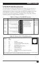
5.1 Status LEDs
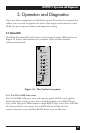
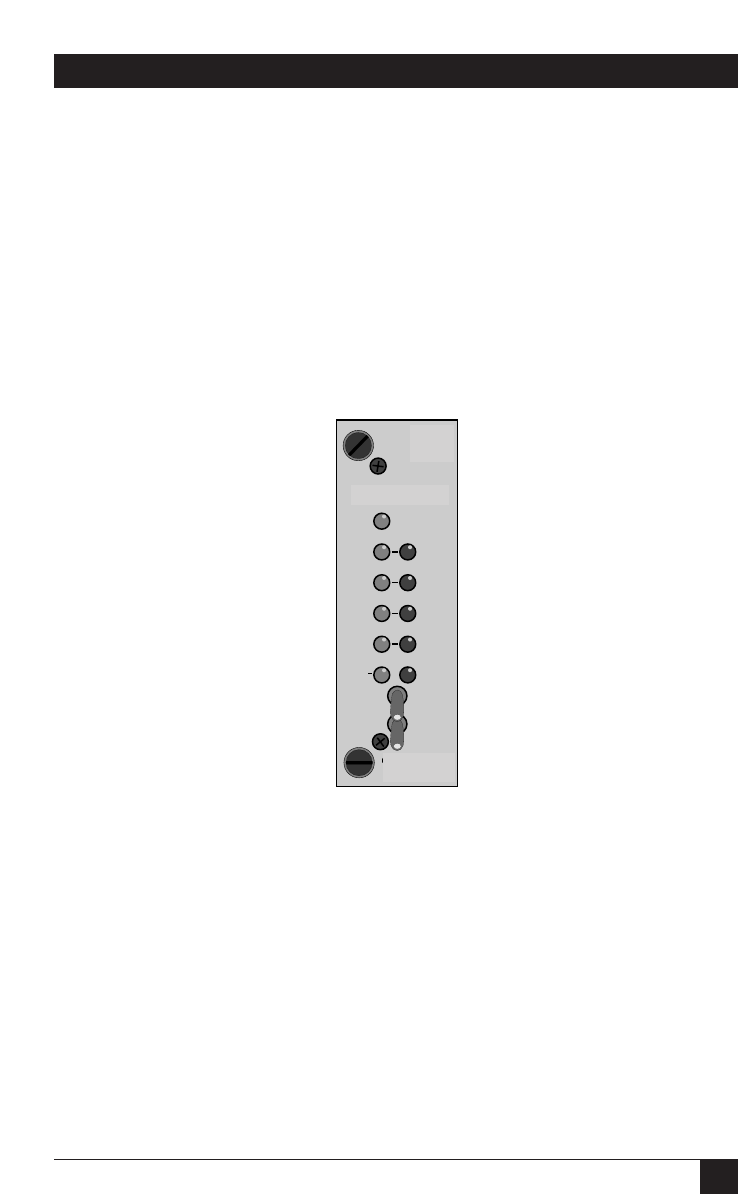
The Multi-Function LD Card features 11 front-panel status LEDs (shown in
Figure 5-1 below) that indicate the condition of the modem and the
communication link.
5.1.1 T
HE
TD
AND
RD I
NDICATORS
The TD and RD indicators (one red and one green LED for each signal)
blink when data activity occurs: The red LEDs indicate a low RS-232 logic
level, while the green LEDs indicate a high RS-232 logic level. Also, since RS-
232 devices idle in a low state, the red LED will be steadily lit if the
connections are correct and the RS-232 device is in an idle state.
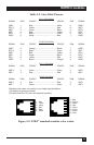
Figure 5-1. The Card’s front panel.
Model 1080RC
Power
TD
RD
CD
RTS
Error
Analog
511
Remote
511/E
Test