


14
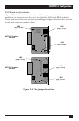
MULTI-FUNCTION LD CARD
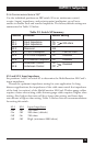
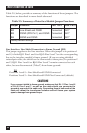
S2 Position 3: V.52 and V.54 Diagnostic Testing
To reset the V.54 circuit, turn switch S2 position 3 ON, then back OFF.
S2-3 Test Mode
Off Normal Operation (default)
On Test Disabled
S2 Positions 4 and 5: RTS/CTS Delay
Set positions 4 and 5 of switch S2 to determine the amount of time the Multi-
Function LD Card waits after it “sees” RTS before it sends CTS. Possible
settings are no delay, 7 ms, or 53 ms.
S2-4
S2-5 RTS/CTS Delay
On On 7 ms (default)
On Off 53 ms
Off On No delay
Off Off No delay
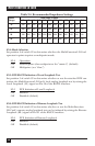
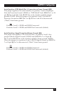
S2-6: Signaling-Rate Range
Set position 6 of switch S2 to determine the degree of asynchronous data-rate
fluctuation that the Multi-Function LD Card will accept (that is, how much
variance from a given frequency level the Card will tolerate).
S2-6
Signaling-Rate Range
Off -2.5% to +1% (default)
On -2.5% to +2.3%
S2-7 and S2-8: Word Length
Set positions 7 and 8 of switch S2 to determine the word length that the Multi-
Function LD Card will expect for synchronous or asynchronous data. For
example, if you are using the most common data format (1 start bit,
8 data bits, 1 stop bit, and no parity), you would use the factory-default word-
length setting (10 bits).
S2-7
S2-8 Word Length
On Off 8 bits
On On 9 bits
Off Off 10 bits (default)
Off On 11 bits