


19
CHAPTER 3: Configuration
3.2.3 W
HERE THE
J
UMPERS
A
RE
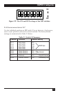
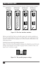
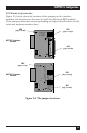
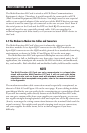
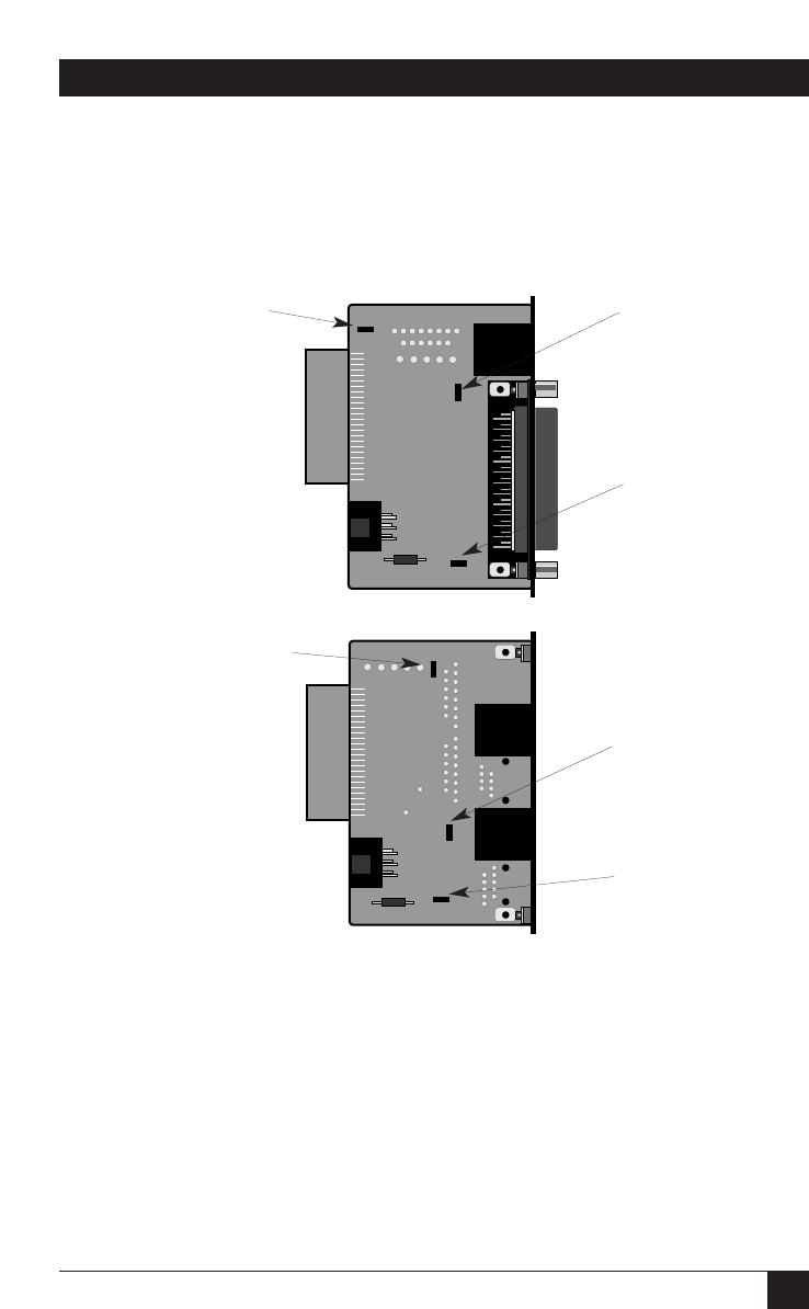
Figure 3-5, below, shows the locations of the jumpers on the interface
modules (the locations are the same for both the -RJ11 and -RJ45 models).
These jumpers determine various grounding and signal characteristics for the
serial and modem-to-modem lines.
Figure 3-5. The jumper locations.
ME758C interface
module
JB2
(peg 1 on left)
JB3
(peg 1 on top)
JB4
(peg 1 on left)
JB2
(peg 1 on top)
JB3
(peg 1 on top)
JB4
(peg 1 on left)
ME759C interface
module