


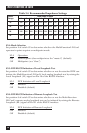

24
MULTI-FUNCTION LD CARD
4.2.3 S
WITCHING THE
P
OWER
S
UPPLY
B
ETWEEN
120
AND
240 V
OLTS
Although the MicroRack is shipped from the factory with a customer-specified
power-supply configuration, you may change the configuration yourself.
Follow these steps to switch the configuration of the power supply between
120 VAC and 240 VAC:
1. Making sure the rack is turned off and unplugged, remove the power
supply’s front module and locate the two-position switch (labeled either
“110/220” or “115/230”) near the back of the card. Slide the switch to
the setting corresponding to your desired voltage.
2. Replace the existing fuses with fuses of the correct type (see step 4 of
Section 4.2.2).
3. If necessary, replace the power-supply cord with a country-specific cord.
(For certain countries, your supplier might be able to give you a special
quote on country-specific cords.) Plug the cord back in.
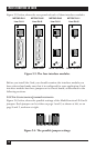
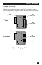
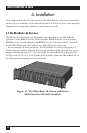
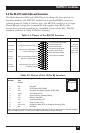
4.3 Installing the Multi-Function LD Card in the MicroRack
The Multi-Function LD Card is made up of a main (front) module and an
interface (rear) module. The two cards meet inside the rack chassis; their
mating 50-pin card-edge connectors plug into each other. Use these steps to
install each Multi-Function LD Card into a MicroRack:
1. Slide the rear module into the back of the MicroRack on the metal rails.
2. Secure the rear module using the included metal screws.
3. Slide the front module into the front of the chassis. It should meet the
rear module when it is almost completely in the chassis.
4. Push the front module gently into the card-edge receptacle of the rear
module. It should “click” into place.
5. Secure the front module using the thumbscrews.
NOTE
Since the MicroRacks allow “hot swapping” of cards, it is not necessary to
power down the rack when you install or remove a Multi-Function LD
Card.