


30
MULTI-FUNCTION LD CARD
5.1.2 T
HE
RTS
AND
CD I
NDICATORS
The RTS and CD indicators (again, one red and one green LED for each
signal) function much like the TD and RD LEDs: The red LEDs light for a
“low” signal, while the green LEDs light for a “high” signal. The RTS LEDs
light for an incoming RTS signal on the RS-232 side (DB25 Pin 4 or 10-pin RJ
Pin 9). The CD LEDs light for an incoming signal on the line side and the
resulting output signal on the RS-232 side (DB25 Pin 8 or 10-pin RJ
Pin 3).
5.1.3 T
HE
P
OWER
I
NDICATOR
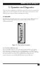
The green Power LED lights to indicate that the Card is receiving power.
5.1.4 T
HE
T
EST
I
NDICATOR
The green Test LED lights to indicate that V.52 or V.54 tests are running.
5.1.5 T
HE
E
RROR
I
NDICATOR
The red Error LED has three functions:
A. When the Card is in test mode (green Test LED is lit), the Error LED
glows red when bit errors occur.
B. When the Card is not in test mode (green Test LEDis dark), the Error
LED is used to indicate an RTS streaming condition (see Section 5.2.2).
C. The Error LED can also indicate line-quality problems (see
Section 5.2.1) such as:
1. The improper use of “flat satin” (non-twisted-pair) cable, or low-
quality twisted-pair cable, to connect the modems.
2. One or more broken wires in the 4-wire twisted-pair cable.
4. Broken or corroded connectors.