Operations MediaVault 4105 User Manual
5-6
MV 4105_Ciprico Inc.
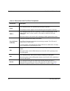
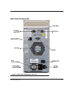
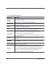
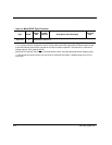
TABLE 5-3. Rear Panel Components.
Component Description
FC Port 1,
FC Port 2
FC Port 1 and FC Port 2 (on Side A or Side B) can accept a Fibre Channel SFP with
an LC Duplex optical cable.
See “Fibre Channel Connections” in Chapter 4, Installation.
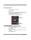
MODE SELECT Used to change the mode (RAID type) number. See “Mode (RAID Type) Change
Procedure” on page 5-12.
Unit Fan
Vents heat from the interior of the MV 4105.
DIAG The Diagnostic port is used to enable firmware downloads or perform special
diagnostics. See “DIAG - Diagnostic Port” in Chapter 4, Installation.
Power On/Off
In the “On” (1) position, the power switch provides power to the MV 4105.
In the “Off” (0) position, the MV 4105 is powered-off.
To completely remove power from the MV 4105, disconnect the power cable from the
power cable receptacle.
MODE SET A multi-function button. See the description in the “Mode Set Button” section on
page 5-13.
Receptacle,
Power Cable
Power receptacle for 100-240 Vac power cable to the auto-ranging power module
(power supply).
Fan, Power Supply Vents heat from the power supply.
Hub LEDs
LINK LED: Indicates that communications are established between the Fibre
Channel microprocessor inside the MV 4105 and the built-in hub of the MV 4105.
SYNC LED: Indicates that the FC speed is established between the built-in hub
portion of the MV 4105 and the device to which this port is connected.
ACTIVE LED: Indicates that data is being transmitted.


