


800-12005V1 - A - 08/2012
Introduction | 33
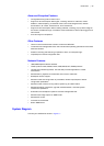
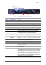
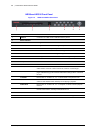
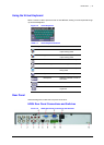
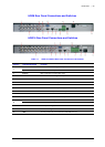
HRG8 Rear Panel Connections and Switches
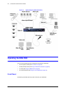
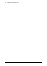
HRG16 Rear Panel Connections and Switches
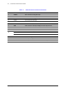
Table 1-6 HRG8 and HRG16 Rear Panel Connections and Switches
Position Connection/Switch Function
1
Main Video Out BNC connectors for analog video input.
Spot Video Out BNC connectors for spot video out
2Video In BNC connectors for analog video input.
3Audio In RCA connectors for analog audio input.
4Line In RCA connector for audio input.
5Audio Out RCA connector for audio output.
6 RS-232 Port DB9 connector for RS232 devices.
7VGA DB15 connector for VGA output. Display local video output and menu.
8LAN Connector for LAN (Local Area Network).
9USB Connector for USB devices.
10 RS-485 Port Connector for RS-485 devices. T+, T- pins connect to PTZ.
11
Alarm In Connector for alarm input.
Alarm Out Connector for alarm output.
12 12 V 12 V DC power supply.
13 Power Switch for turning On/Off the device.
14 GND Ground (needs to be connected when HRG DVR starts up).