


Page 23
ADVANCED OPERATION
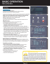
ALARM
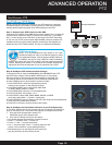
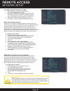
Video Blind
Video Blind is a feature that detects when the camera is covered or
is being obstructed by light with the inability to capture live camera
viewing. There are 6 sensitivity settings from Lowest to Highest. You
are given the option of being informed of this event through Email or
with the alarm status screen displayed. Click OFF or On to enable.
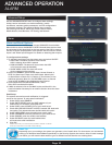
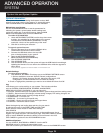
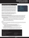
Alarm Management
DELAY setting is the amount of time that recording
will continue after the alarm is cleared.
ALARM OUTPUT sets the amount of time the output relay
contact will stay activated after the alarm is cleared.
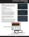
Alarm Inputs:
Alarm inputs are devices or switches that activate when a door,
window, cabinet etc. is opened or accessed. For example, you
might want to only have the camera record when someone opens
a tool cabinet or when a door opens vs. recording when motion
occurs around those areas. There may be people moving by those
areas frequently but you are only concerned about when those
areas are accessed. This saves hard drive space and makes it
easier to find an event that was recorded to the hard drive.
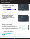
See Alarm Inputs Configuration diagram at the bottom. Use the
GND from the alarm block on the DVR and connect to Common
of the sensor device. Then using the NO or NC of the sensor
device and connect to the appropriate Alarm In 1,2,3,or 4.
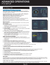
Alarm Ouput:
Alarm output is used to activate an external device such as a horn or
light after an alarm is triggered. To do this the DVR uses a dry contact
normally open relay. To configure alarm ouputs, connect the external
device to the NO (Normally Open) and COM (Common) connections
on the alarm block as required by the device. The maximum contact
rating is 24 VDC @ 2 A. Alarm input can start recording only on the
camera # that coincides with the alarm input # (cameras 1,2,3,on 4).
Alarm Manage Screen
Video Blind Screen
From NO or NC depending on setup
selected to alarm inputs 1 through 4
COM
NO
NC
Example Device:
Door Sensor
Use GND from
alarm block
to COM
Alarm Inputs Conguration
Note: Ground must be connected to GND in alarm block for device to operate properly
ALARM_COM
ALARM_NO
GND
ALARM_IN1
ALARM_IN2
GND
ALARM_IN3
ALARM_IN4
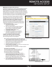
Alarm Status