3-2 IC697VAL348 8-Channel, 16-bit Digital-to-Analog Converter Board User’s Manual GFK-2059
– December 2001
3
Introduction to Programming the Digital-to-Analog Converter
Board
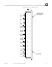
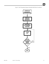
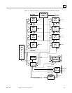
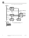
The Digital-to-Analog Converter Board is memory mapped in the short I/O address space. The
board occupies 16 successive word locations in the VME short I/O address space of 65,535 bytes.
Only the first nine word locations are actually used by the board. The short I/O space is located
from XXXX0000 HEX to XXXXFFFF HEX. The address bits A31 to A16 are CPU dependent.
Each Read cycle may be either a word or byte transfer. The board base address may be selected by
DIP switches as shown in “Board Address Selection Switches” on page 2-5. Tables 3-1 and 3-2
below represent the DAC address map assuming the factory set base address of XXXX0060 HEX.
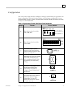
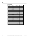
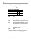
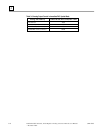
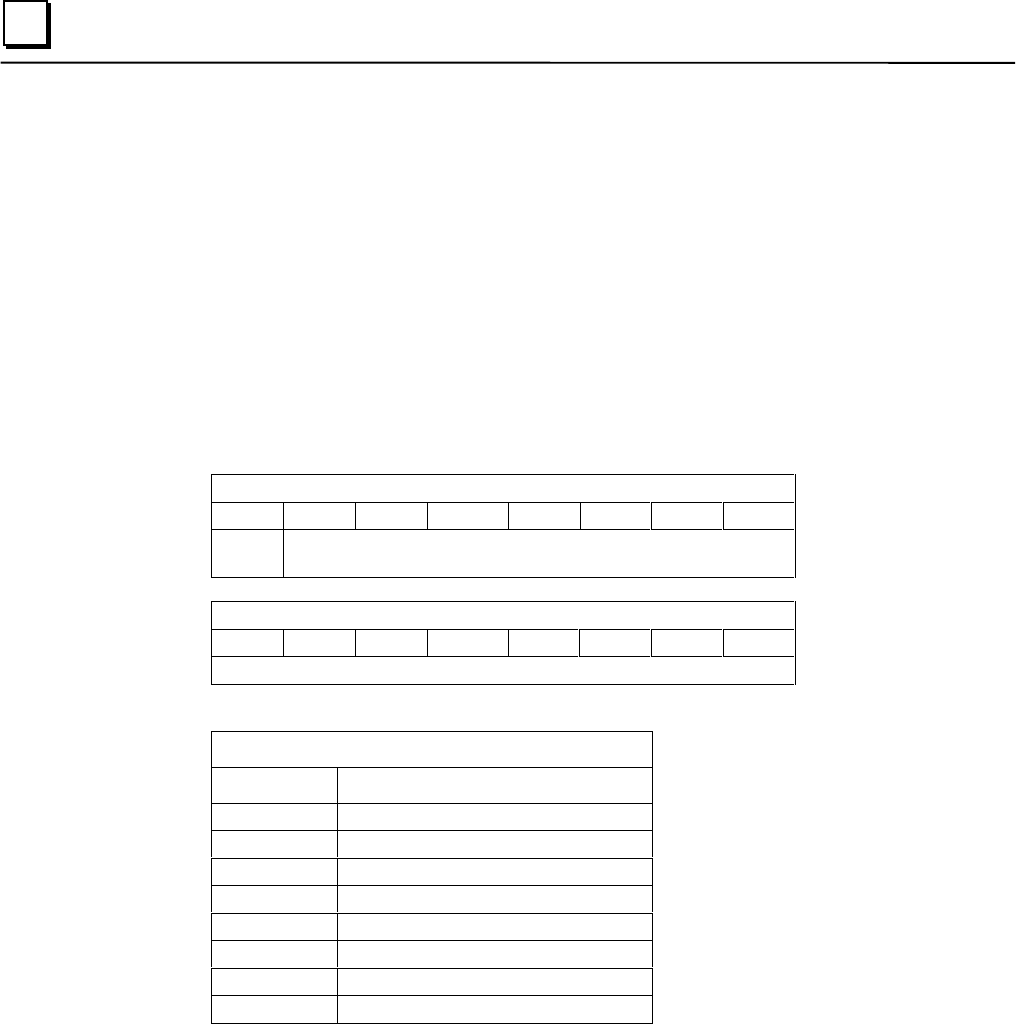
Table 3-1:Control and Status Register
Control and Status Register (CSR) (Read/Write) Address $XXXX0070
D15 D14 D13 D12 D11 D10 D09 D08
Not
Used
Control and Status Bits
Control and Status Register (CSR) (Read/Write) Address $XXXX0070
D07 D06 D05 D04 D03 D02 D01 D00
Not Used
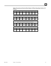
Table 3-2: DAC Channels Address Map
DAC Channels (0 to 7) Address (Write Only)
Address D15 (MSB) D00 (LSB)
XXXX0060 DAC OUT 0
XXXX0062 DAC OUT 1
XXXX0064 DAC OUT 2
XXXX0066 DAC OUT 3
XXXX0068 DAC OUT 4
XXXX006A DAC OUT 5
XXXX006C DAC OUT 6
XXXX006E DAC OUT 7
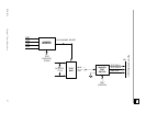
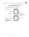
Note
Jumper JC determines whether the board operates in Short Supervisory I/O
Access or Short NonPrivileged I/O Access. With the jumper installed Short
NonPrivileged I/O Access is selected.
Tables 3-1 and 3-2 above shows addressing information for 16-bit word transfers. Data may be
transferred to the DACs in 8-bit format. When using byte format, the low byte is always transferred
first then the high byte next. For example, assuming a board base address of XXXX0000 HEX, a
low byte transfer (D7 to D0) to Channel 0 is written to address XXXX0001 HEX. The high byte of
data (D15 to D8) is then written to address XXXX0000 HEX.