


GFK-2059 Chapter 3 Programming 3-7
3
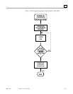
Test Mode Programming
Any of the eight DAC outputs may be selected to pass to an ADC board over test bus 2 to verify
the DAC outputs. If a MUX is present in the analog backplane then any DAC output can be
selected to go to that board for test purposes over test bus 1. Generally the programming sequence
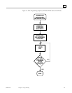
for utilizing one of the two test buses is as follows:
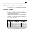
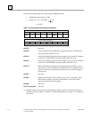
If IMMEDIATE DAC UPDATE MODE is employed, then a Control Word should first be written
to the CSR. This Control Word information includes which test bus the DAC output is to be routed
to, and whether the output is to be isolated or connected to the P3 connector (refer to Table 3-4 on
page 3-4 and Table 3-5 on page 3-5). The DAC to be updated is then loaded with a 16-bit word.
The channel is updated and passes out the selected test bus.
An output may also be updated under program control to route to a specified test bus. The board
must have previously been jumpered to accommodate the DELAYED DAC UPDATE MODE as
shown in “Program Controlled and External Start Convert Mode” on page 2-9. The programming
sequence is as follows:
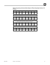
First, a 16-bit word or two 8-bit bytes are written to the address of the DAC channel that is to be
updated. The data is stored in the DAC Register and will be converted by setting the proper bits in
a Write cycle to the CSR. The CSR must be written to at the same address as that of the DAC
channel that has previously been loaded plus 10 HEX. For example, if the user wanted to convert
Channel no. 2 which was written to address XXXX0062 HEX, then the Control Word would be
written to address XXXX0072 HEX (XXXX0062 and 10 HEX). Data bit D09 when written as
"one" to the CSR initiates the analog conversion of the previously stored 16-bit word.
The test modes can only be used if an ADC board exists in the same GE Fanuc analog (P2)
backplane as the Digital-to-Analog Converter Board.