


12
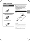
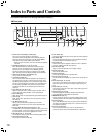
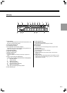
Index to Parts and Controls
MODEL NO.
DPS
-
8.3
SACD
&
DVD AUDIO/VIDEO PLAYER
REMOTE
CONTROL
COMPONENT
2
IR
DIGITAL
OUTPUT
OPTICAL COAXIAL
OUT
IN
S VIDEO VIDEO
Y
P
B
P
R
COMPONENT
1
VIDEO
OUTPUT
ANALOG
OUTPUT
L
R
L
R
SURR
11
+
2
CH 1 CH 2 FRONT SURR 1 CENTER SURR 2
SUB
WOOFER
TRIG
-
GER
OU
T
RS-232
AC
INLET
12
V
Y
P
B
P
R
1
2
3
4
@
~
7
9
8
0
-
=
!
5
6
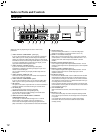
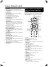
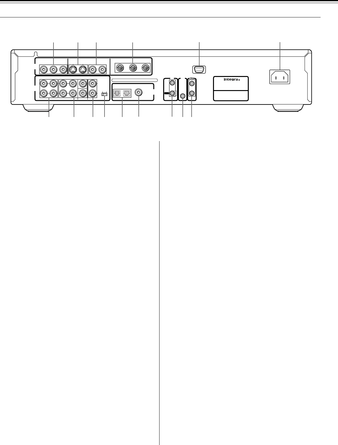
1 VIDEO OUTPUT COMPONENT 1 jacks [16]
If your TV has component inputs, you can connect a component
video cable to your TV and to your DVD Player for ideal video
quality. The component Video Cable only carries the video signal;
remember to connect the left and right audio cables. If you connect
a TV that is compatible with a Progressive scan signal, you can
enjoy both Interlaced and Progressive scan.
2 VIDEO OUTPUT S VIDEO jack [16]
If your TV or monitor has an S-video input, clear picture
reproduction is possible by connecting the player to your TV or
monitor via the S-Video jack.
You can switch between [S1] and [S2] S-video output from the
Setup menu.
3 VIDEO OUTPUT VIDEO jack [15]
Connect to the video input on a TV or monitor or AV amplifier or
receiver with video input capability.
4 VIDEO OUTPUT COMPONENT 2 jacks
If your TV has component inputs, you can connect a BNC video
cable to your TV and to your DVD Player for ideal video quality.
5 RS-232 port
This port is to be used in conjunction with an external controller to
control the operation of the DPS-8.3 using an external device.
6 AC INLET [20]
Use to connect the power cord to the wall outlet.
7 ANALOG OUTPUT CH 1/CH 2 jacks [15-18]
Use to output two-channel audio (analog) to the audio stereo
inputs on a TV or stereo amplifier.
8 ANALOG OUTPUT FRONT/SURR 1/CENTER/
SUBWOOFER jacks [18]
Use to output 5.1 channel audio (analog) to the 5.1 channel
discrete inputs on an amplifier. If you are connecting to a
receiver that has both digital and analog input jacks for DVD
player connection, it may be beneficial to make both connections.
9 SURR 2 jacks [18]
Use when making connections to 7.1 channel analog inputs.
(Make sure the SURR 1/1+2 selector switch is set to 1+2.)
0 SURR 1/1+2 selector switch [18]
When using 2 channel surround, select 1, when using 4 channel
surround, select 1+2. Audio will be output 3dB lower when 1+2 is
selected. The same audio is output from SURR 1 and from
SURR 2.
- DIGITAL OUTPUT OPTICAL jack [17]
Use to output the digital audio signal recorded on discs. You can
output the digital signal via the optical output jack to an AV amplifier
or receiver.
= DIGITAL OUTPUT COAXIAL jack [17]
Use to output the digital audio signal recorded on discs. You can
output the digital signal via the coaxial output jack to an AV
amplifier or receiver.
~ IR IN/OUT jacks [19]
If the DPS-8.3 is located inside a rack or cabinet that will not allow
infrared beams to reach the IR sensor, you will need to connect a
remote sensor to IR IN jack to be able to use the remote controller.
Then install the remote sensor in an unblocked location where you
can easily point the remote controller.
Using a mini-jack connector, connect IR emitter to the IR OUT jack
on the DPS-8.3 and then place the IR emitter on the remote sensor
of the component or facing it.
! 12V TRIGGER jack
When the DPS-8.3 is turned on, this terminal outputs at 12 V/100
mA.
@ z jack [17, 18]
Use to connect this player to another component bearing the z
mark. This lets you control this unit as though it were a component
in a system.
(The components will not function as a system with only z
connections. Be sure to connect the audio connection cables
correctly as well).
■ Rear panel
Shapes of jacks vary depending on the area in which it was
purchased.