


Masterpage:Right-No-Heading
15
Filename [XVS20EK_06Index.fm]
Page 15 March 28, 2003 6:55 pm
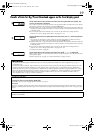
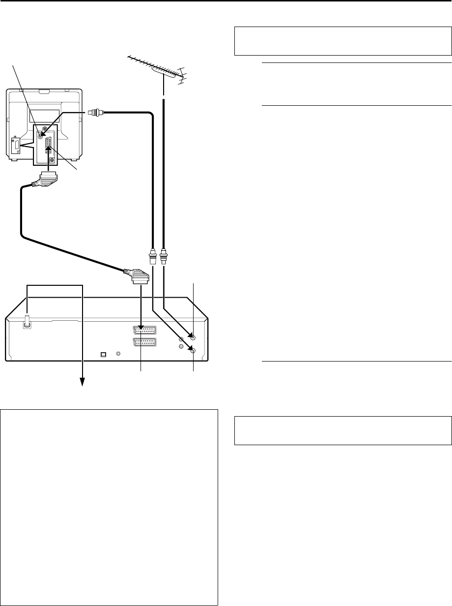
Basic Connections
It’s essential that your unit be properly connected.
A
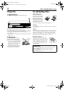
Situate the unit.
Place the unit on a stable, horizontal surface.
B
Connect the unit to TV.
The connection method you use depends on the type of
TV you have.
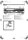
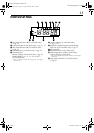
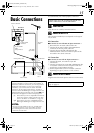
RF Connection
8
To connect to a TV with NO AV input connectors —
A
Disconnect the TV aerial cable from the TV.
B
Connect the TV aerial cable to the ANTENNA IN
connector on the rear panel of the unit.
C
Connect the provided RF cable between the
ANTENNA OUT connector on the rear panel of the
unit and the TV’s aerial connector.
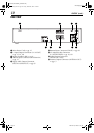
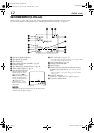
AV Connection
8
To connect to a TV with AV input connectors —
A
Connect the aerial, unit and TV as per “RF
Connection”.
B
Connect an optional 21-pin SCART cable between the
L-1 IN/OUT connector on the rear panel of the unit
and the TV’s 21-pin SCART connector.
C
Set the output mode for the L-1 IN/OUT connector
depending on type of your TV. (
੬
left column)
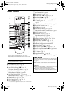
C
Connect the unit to mains.
Plug the end of the mains power cord into a mains outlet.
Make AV connection if your TV has a 21-pin AV input
connector (SCART) in order to reduce the possibility of
interference. With AV connection, you can enjoy stereo
playback of video tapes if you are using a stereo TV.
In addition, if you connect the unit to the TV’s RGB
connectors, set the output mode for the L-1 IN/OUT
connector so that the RGB signal is output from the unit.
When the DVD deck is selected, press and hold
8
until
the desired mode appears on the front display panel.
yc
: Select when your TV is compatible with the Y/C
signal. Y/C signal is output from the unit. Also
set “L-1 OUTPUT” to “S-VIDEO”. (
੬
pg. 62)
rgb
: Select when your TV is compatible with the
RGB signal. RGB signal is output from the unit.
NOTES:
●
Set your TV to the VIDEO (or AV), Y/C, or RGB mode
according to the type of your TV’s SCART connector.
●
For switching the TV’s mode, refer to the instruction
manual of your television.
Aerial connector
Back of TV
21-pin SCART
connector
TV aerial
cable
RF cable
(provided)
21-pin SCART
cable
(not provided)
Mains power cord
Mains outlet
Back of unit
L-1 IN/OUT
ANTENNA
IN
ANTENNA
OUT
THESE STEPS MUST BE COMPLETED BEFORE ANY
VIDEO OPERATION CAN BE PERFORMED.
After the connection is completed, perform “Auto Set
Up” on page 16.
XVS20EK_01.book Page 15 Friday, March 28, 2003 7:00 PM