


18
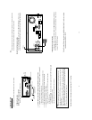
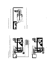
3.2 Hard-Disk Drive Installation
The DVR is equipped with two compartments of hard-disk drive. The unit usually comes with one
hard-disk drive installed in the compartment HD1, which is default-configured as a master. If you need
a second hard-disk drive to be installed in the compartment HD2 (Mobile), please contact your
distributors or installers for specific instructions on how to install it. Please don’t serve yourself before
consulting your installers. If there is only one hard-disk drive in the mobile compartment, please set the
HD2 USAGE option to REC (Please refer to section 5.5) before proceed recording function. The
jumper-settings arrangement of installed hard-disk drives for the system (Table 3.2 A.) is shown in the
tables below.
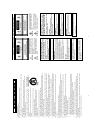
Table 3.2 A. The jumper settings of hard-disk drives in the system
Location Jumper
IDE 1 Compartment HD 1 Master (Default)
IDE 2 Compartment HD 2 Master
Table 3.2 B. Compatible hard-disk drives
Manufacturer Model Capacity Rotation
ST380020A/P 80GB 5400 RPM
Seagate
ST340810A/P 40GB 5400 RPM
4A160J0-1A 160GB 5400 RPM
4R080L0-1 80GB 5400 RPM
Maxtor
6Y120L0-1 120GB 7200 RPM
NOTE: Hard-disk drives not shown on this list have not been tested by the engineering team
and are not recommended for use with this product. For the latest updated list on the
recommended hard-disk drives, please contact your dealers or distributors.
19
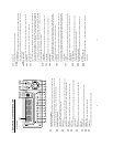
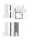
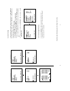
3.3 System Information
You can display system settings information as shown on Table 3.3 A below at any time by pressing
the Display button
. In the playback mode, the recorded video information is displayed. In the live or
recording mode, the Manual Recording information is displayed. However, when the DVR is displaying
a decoded image from a multiplexer, you must first switch the unit to encoded image displaying (The
pictures is switching swiftly and the light of Monitor button
is off) by pressing the Monitor button
. Each sequential press of the Display button displays a different message detailed in the
following example. By default, the unit displays time, date, and an indicating bar of capacity status on a
monitor as shown next.
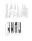
Default display
(Capacity Used) (Capacity Remaining)
09-05-2003 16:13:02
(System Time)
(Date)
The TOP
of the HDD
Current
Position
The END
of the HDD
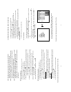
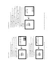
Press the Display button
once; the DVR will display the following sample message plus the default
display. Press the Display button
again; the unit will not display any OSD message. Press the
button one more time to back to the default display.
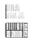
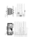
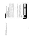
Table 3.3 A. Description of Table 3.3 A
(1+2: 59G): Total capacity of installed hard-disk, 59 GB
(12.4 HR): Total 12.4 hour recording time available
(
): Timer record activated
(
): Alarm record activated
(QUALITY: BEST): Record quality setting, BEST
(NTSC): NTSC system
(RATE: 6 HR): Setting of Record time mode, 6 hours
(20 F/S): Record speed setting, 20 fields/sec
(MUX: OFF):
Only connected to a single camera.
( ): Audio function activated
(
): Indicate which HDD is activated
(9K): The image file size
(HD): Hard-disk Compartment
(P): Y Hard-disk installed; . No hard-disk installed
(SIZE 20G): The capacity of the installed hard-disk
(POS): Percentage of system; R: Recording; P: Playback
(IP : 192 . 168 . 1 . 90): Setting of
the Ethernet
communication,192.168.1.90
(
): External signal
(
X): Cannot operate at now
* About the location of the buttons, please refer to Page 10 2.1 Front View.
1+ 2: 59G 12.4 HR
QUALITY: BEST NTSC
RATE: 6 HR 20 F/S
MUX : OFF 9K
HD P SIZE POS
1 Y 20 G 39.5% P
2 Y 39 G 0.0% R
IP : 192 . 168 . 1 . 90