


62
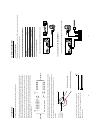
Physical specification for Ethernet
Wire Type
Cat. 5
Connector Type
RJ-45
Max. Cable Length
30 m
Hub Wiring Configuration
Straight Through
PC Wiring Configuration
Cross Over
NOTE: For more details on network connections, please refer to the following document.
10.1.2 Install the Network Viewer in your PC
Install the Network Viewer from the supported CD-R.
1. Exit all applications currently running in the selected PC.
2. Insert the supported CD-R in the CD-ROM drive. The program will execute the installation
automatically. Follow the on-screen instructions to proceed with the rest of the installation
procedure as they appear.
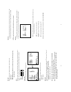
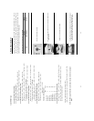
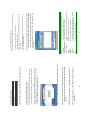
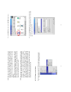
3. After the installation is complete, pop up the START menu from your computer, and point to
Programs / JVC Picture Viewer to open up the program selection page as shown below.
Click the Network Viewer tag to start the Network Viewer program.
NOTE: The number of Network Viewer that can be simultaneously connected to VR-601 is one.
NOTE: If the Network Viewer needs to be upgraded, please contact your JVC dealer.
NOTE: Please make sure the TCP/IP communication software has been properly set and
configured in your computer. To check your TCP/IP settings, refer to the following
document.
NOTE: When the Alarm Operation is ON, The image software (Network Viewer) doesn't
show the pictures and a message will be displayed.
NOTE: The maximum refresh rate on live mode (REC or STOP) is 2F/S. It depends on the
network speed.
63
10.1.3 View the VR-601 video from a remote PC
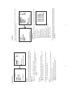
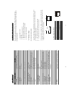
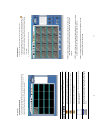
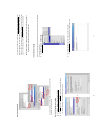
Follow the instructions below to use the Network Viewer to browse a VR-601 video from a
remote location. Upon entering the Network Viewer; the connection box will appear as follows.
1. Choose a channel number from the Channel drop-down list.
2. Assign a name for the chosen VR-601.
3. Type in the password and IP of the device and click the Add tag to add the device to the
connection list.
4. Click the Connect tag to establish the connection between the devices and the computer.
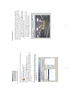
Click OK to begin viewing images.
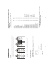
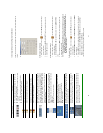
NOTE: Upon connection, the connection status box indicates the name and IP address
of the selected device. If there’s a failure to connect, a “Fail” message appears
on the screen right after the device IP address; otherwise an “OK” appears. To
add more connections or units to the VR-601, please repeat the above
instructions.
Functions
Description
zChannel
Assign a display location when you have multiple devices connected.
zName
This box allows you to assign a name to the chosen device.
zPassword
Type the preset password for making a connection.
zURL of the Remote Device
Type the IP address which you preset for the device
zURL of a Proxy
Type your proxy server address when accessing the Internet via a proxy
server.
zPort
Enter the designated port setting of your proxy server.
zModify
Click to change the settings of a chosen device.
zDelete
Click to remove the connection of a chosen device
zConnect
Click to establish the connection between the devices and the computer.
zOK
Click to access the display page of the Network Viewer
zCancel
Click to exit the program of the Network Viewer.