


21
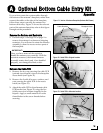
Route and Secure the Cables
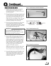
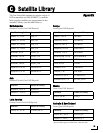
1. Remove the four M4 screws securing the
cable brackets to the inside rim of the
baseplate (see Figure 37). Remove and save
the cable brackets.
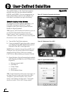
2. Route the data/power (F-type connector end)
and RF cables belowdecks through the cable
access hole. Leave an adequate service loop,
approximately 8" (20 cm) of slack, in the
cables for easy serviceability. Later, you will
connect the data/power cable to the MCU
and the RF cable(s) to the receiver(s).
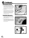
3. Route the N-type connector end of the data/
power cable (see Figure 38) through the
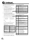
baseplate’s bottom cable access hole. Connect
the data/power cable to the center connector
on the cable PCB (see Figure 39).
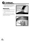
4. Route the RF cable(s) through the baseplate’s
bottom cable access hole. Using a 9/16"
wrench, connect the RF cable(s) to the cable
PCB (see Figure 39). If you need to connect
only one RF cable, connect the cable to the
RF1 connector. Connect any additional RF
cables to the RF2, RF3, and RF4 connectors.
See Step 4e on page 6 to determine the
number of RF cables required.
TIP: If you connect two or more RF cables, label
both ends of each cable to match the connector.
This will make it easier to identify the cables later.
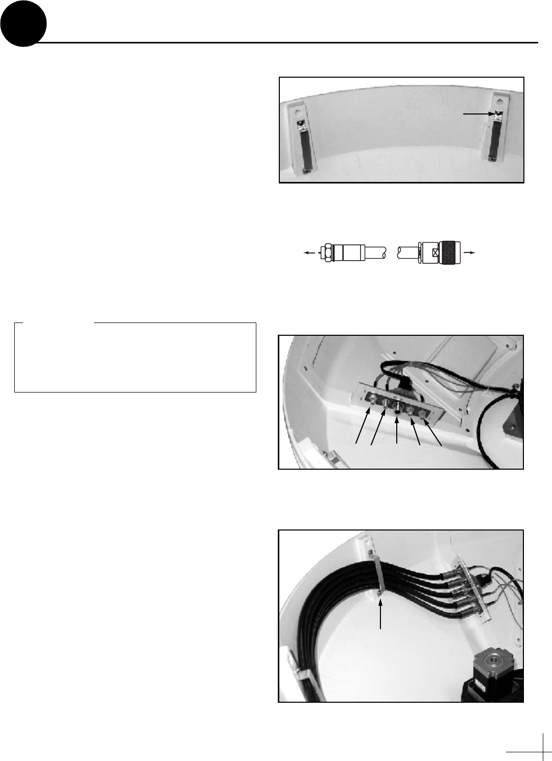
5. Secure the data/power and RF cables to the
inside rim of the baseplate, using the two
cable brackets. Secure the brackets in place
using the four M4 screws you removed
earlier (see Figure 40).
Figure 37: Cable Brackets on Inside Rim of Baseplate
M4 Screw (x4)
F-type Connector N-type Connector
MCU Antenna
Figure 38: Data/Power Cable Connections
Figure 39: Cable Connections on PCB
Data/RF4 RF2 RF1 RF3
Power
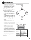
Be sure to properly align the data/power
cable with the PCB connector before
tightening. Connecting the cable at an angle
may damage the cable’s center tines.
IMPORTANT!
Figure 40: Cables Secured by Brackets
M4 Screw (x4)
Continued...
A