


3
Before you begin, follow these steps to make sure
you have everything you need to complete the
installation.
a. Unpack the box and ensure it contains
everything shown on the Kitpack Contents
List. Save the packaging for future use.
b. Carefully examine all of the supplied parts to
ensure nothing was damaged in shipment.
c. Gather all of the tools and materials listed
below. You will need these items to complete
the installation.
• Flat-head and Phillips-head screwdrivers
• Electric drill and 1/2" (13 mm) and #29
drill bits
•17 mm socket wrench
• 9/16" open-end wrench
• Light hammer and center punch
•Adhesive tape
• Scriber or pencil
• Wire strippers
• 15-amp quick-tripping circuit breaker
• RG-6 or RG-11 RF coax cable(s) with
Snap-N-Seal
®
F-connectors for
connecting the antenna to the receiver(s)
(see Step 4e on page 6 to determine the
number and type of cables required)
• Connector installation tool (Augat IT1000
- KVH part #19-0242)
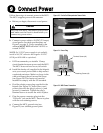
• Power cable for connecting vessel power
to the MCU (see Figure 2)
• Satellite TV receiver and TV
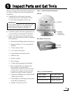
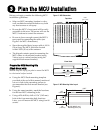
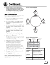
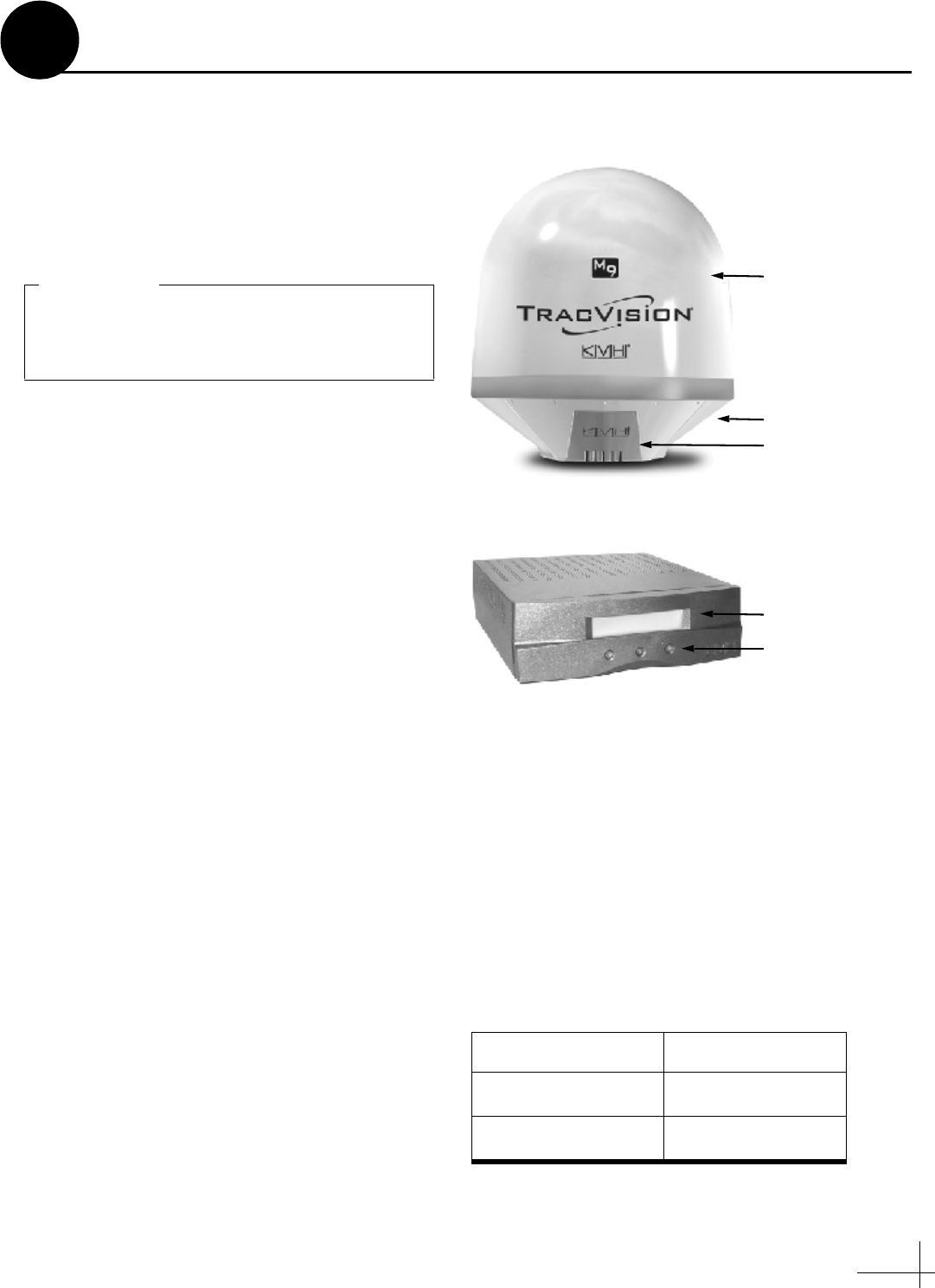
Radome
Baseplate
Connectors
Figure 1: TracVision M9 System Components
(w/Logo Plate)
Antenna
MCU (Master Control Unit)
Display
Buttons
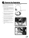
Always lift the antenna by the baseplate and
never by the radome or any portion of the
internal antenna assembly (see Figure 1).
IMPORTANT!
Figure 2: Power Cable Guidelines
Cable Length Use Cable Gauge
< 40 ft (12 m)
12AWG (4mm
2
)
40-70 ft (12-21 m)
10AWG (6mm
2
)
Inspect Parts and Get Tools
1